The Microscopy
IntroductionThe microscope has been a valuable tool in the development of scientific theory and study of cells, microbes, etc., there are various types of microscopes available depending upon their use and functionality. A compound microscope is composed of 2 elements; a primary magnifying lens and a secondary lens system. Light passes through an object and is then focused by the primary and secondary lens. If the beam of light is replaced by an electron beam, the microscope becomes a transmission electron microscope. If light is bounced off of the object instead of passing through, the light microscope becomes a dissecting scope. If electrons are bounced off of the object in a scanned pattern, the instrument becomes a scanning electron microscope.
The function of any microscope is to enhance resolution. The microscope is used to create an enlarged view of an object so that we can observe details not otherwise possible with the human eye. Because of the enlargement, resolution is often confused with magnification, which refers to the size of an image. In general, the greater the magnification, the greater the resolution, but this is not always true. There are several practical limitations of lens design that can result in increased magnification without increased resolution.
If an image of a cell is magnified from 10X to 45X, the image gets larger, but not necessarily any clearer. The image on the left is magnified with no increase in resolution. The image on the right is magnified the same, but with increasing resolution. Note that by the time the image is magnified 10X (from 10X to 100X), the image on the left is completely unusable. The image on the right, however, presents more detailed information. Without resolution, no matter how much the image is magnified, the amount of observable detail is fixed, and regardless of how much you increase the size of the image, no more detail can be seen. At this point, you will have reached the limit of resolution
or the resolving power of the lens. This property of the lens is fixed by the design and construction of the lens. To change the resolution, a different lens is often the only answer.
The reason for a dichotomy between magnification and resolution is the ability of the human eye to see 2 objects. It is necessary that 2 objects be about 0.1-mm apart when held 10" from the face in order for us to detect them as 2 objects. If they are closer than 0.1 mm, we will perceive them as a single object. If 2 objects are 0.01-mm apart, we cannot detect them unless we magnify an image of them by 10X. What has happened is that we have effectively altered our resolution ability from 0.1 mm to 0.01 mm through the use of a magnifying lens. Our limit of resolution has changed from 0.1 mm to 0.01 mm, or inversely, our resolving power (resolution) has increased by a factor of 10.
How to Use The Microscope
- Moving and transporting the microscope. Grasp the arm of the microscope
with one hand and support the base of the microscope with the other.
Handle it gently.
- Before you plug in the microscope, turn the voltage control dial on the right side of the base of the microscope to 1. Now plug in the microscope and use the on/off switch in the front on the base to turn it on.Make sure the entire cord is on the bench top and not hanging down where it could be caught on a leg. Adjust the voltage control dial to 10.
- Adjusting the eyepieces. These microscopes are binocular; that is, they have
2 ocular lenses (eyepieces). To adjust them, first find the proper distance
between your eyes and the eyepieces by closing one eye and slowly moving
your head toward that eyepiece until you see the complete field of view—
about 1 inch away. Keep your head steady and both eyes in the same
plane. Now open the other eye and gradually increase the distance between
the eyepieces until it matches the distance between your eyes. At the
correct distance, you will see one circular field of view with both eyes.
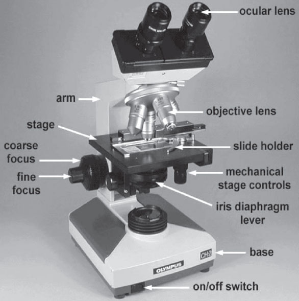
Figure 1 Olympus microscope.
- Positioning the slide. Place the slide specimen-side-up on the stage so that the specimen lies over the opening for the light in the middle of the stage. Secure the slide between, not under, the slide holder arms of the mechanical stage. The slide can now be moved from place to place using the 2 control knobs located under the stage on the right of the microscope.
- Adjusting the illumination:
- Adjust the voltage by turning the voltage control dial located in the rear righthand side of the microscope base. For oil immersion microscopy (1000X), set the light on 9 or 10. At lower magnifications, less light will be needed.
- Adjust the amount of light coming through the condenser using the iris diaphragm lever located under the stage in the front of the microscope. Light adjustment using the iris diaphragm lever is critical to obtaining proper contrast. For oil immersion microscopy (1000X), the iris diaphragm lever should be set almost all the way open (to your left for maximum light). For low powers such as 100X, the iris diaphragm lever should be set mostly closed (to your right for minimum light).
- The condenser height control (the single knob under the stage on the left hand side of the microscope) should be set so the condenser is all the way up.
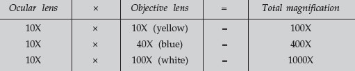
- Obtaining different magnifications. The final magnification is a product of the
2 lenses being used. The eyepiece or ocular lens magnifies 10X. The objective
lenses are mounted on a turret near the stage. The small yellow-striped lens magnifies 10X; the blue-striped lens magnifies 40X, and the white-striped oil
immersion lens magnifies 100X. Final magnifications are as follows:
- Focusing from lower power to higher power:
- Rotate the yellow-striped 10X objective until it locks into place (total magnification of 100X).
- Turn the coarse focus control (larger knob) all the way away from you until it stops.
- Look through the eyepieces and turn the coarse focus control (larger knob) toward you slowly until the specimen comes into focus.
- Get the specimen into sharp focus using the fine focus control (smaller knob) and adjust the light for optimum contrast using the iris diaphragm lever.
- If higher magnification is desired, simply rotate the blue-striped 40X objective into place (total magnification of 400X) and the specimen should still be in focus. (Minor adjustments in fine focus and light contrast may be needed.)
- For maximum magnification (1000X or oil immersion), rotate the bluestriped 40X objective slightly out of position and place a drop of immersion oil on the slide. Now rotate the white-striped 100X oil immersion objective into place. Again, the specimen should remain in focus, although minor adjustments in fine focus and light contrast may be needed.
- Cleaning the microscope. Clean the exterior lenses of the eyepiece and objective before and after each lab using lens paper only. (Paper towels may scratch the lens.) Remove any immersion oil from the oil immersion lens before putting the microscope away.
- Reason for using immersion oil. Normally, when light waves travel from one
medium into another, they bend. Therefore, as the light travels from the
glass slide to the air, the light waves bend and are scattered, similar to the
“bent pencil” effect when a pencil is placed in a glass of water. The
microscope magnifies this distortion effect. Also, if high magnification is
to be used, more light is needed.
Immersion oil has the same refractive index as glass and, therefore, provides an optically homogeneous path between the slide and the lens of the objective. Light waves thus travel from the glass slide, into glass-like oil,
into the glass lens without being scattered or distorting the image. In other words, the immersion oil “traps” the light and prevents the distortion effect that is seen as a result of the bending of the light waves.
Bright-Field, Dark-Field, Phase Contrast
All microscopes actually allow visualization of objects through minute shifts in the wavelength phase as the light passes through the object. Further image forming can be had through the use of color, or through a complete negative image of the object. If the normal phase shift is increased (usually by ¼ wavelength), then the microscope becomes a phase contrast microscope. Phase contrast microscopes can be designed to have medium-phase or dark-phase renditions, by altering the degree of additional shift to the wavelength from ¼ to ½ wavelengths, respectively.
If the beam of light is shifted in phase by a variable amount, the system becomes a differential interference contrast microscope.
If the light image is reversed, then the microscope becomes a dark-field microscope. All standard bright-field microscopes can be readily converted to dark-field by inserting a round opaque disk beneath the condenser. Dark-field microscopy was first utilized to examine transfilterable infectious agents, later to be termed viruses, and to determine that they were particulate in nature.
Small objects, even those below the limits of resolution, can be detected easily with dark-field, as the object appears to emit light on a dark-field. (Look at the sky for a comparison. It is fairly easy to see stars in a dark sky, but impossible during the day. The same is true for dark-field versus bright-field microscopy).
Finally, if the normal light microscope is functionally turned upside down, the microscope becomes an inverted microscope. This is particularly useful in tissue culture, since it allows observation of cells through the bottom of a culture vessel, without opening the container, and without the air interface normally present between the objective and the surface of the culture. By adding phase contrast optics to the inverted microscope, it is possible to monitor tissue cultures directly, without the aid of stains or other enhancements.
The Electron Microscope
The transmission electron microscope (TEM) has resolving power (3–10 Å). The scanning electron microscope (SEM) is becoming increasingly popular with cell biologists because of its remarkable ability for quantifiable mapping of surface detail, along with improved resolution (30–100 Å) and its ability to show 3D structure.
The transmission electron microscope is identical in concept to the modern binocular light microscope. It is composed of a light source (in this case an electron source), a substage condenser to focus the electrons on the specimen, and an objective and ocular lens system. In the electron microscope, the ocular lens is replaced with a projection lens, since it projects an image onto a fluorescent screen or a photographic plate. Since the electrons do not pass through glass, they are focused by electromagnetic fields. Instead of rotating a nosepiece with different fixed lenses, the EM merely changes the current and voltage applied to the electromagnetic lenses.
The size of an electron microscope is dependent upon 2 factors. The first is the need for a good vacuum through which the electrons must pass (it takes less than 1 cm of air to completely stop an electron beam). Peripheral pumps and elaborate valve controls are needed to create the vacuum. A substantial electrical potential (voltage) is also needed to accelerate the electrons out of the source. The source is usually a tungsten filament, very much like a light bulb, but with 40–150 killovolts of accelerating voltage applied to an anode to accelerate the electrons down the microscope column. Modern electronics have produced transformers that are reasonably small but capable of generating 60,000 volts.
Another characteristic of electron microscopes is that they are usually designed upside down, similar to an inverted light microscope. The electron source is on top, and the electrons travel down the tube, opposite light rays traveling up a microscope tube. This is merely a design feature that allows the operator and technicians ease of access to its various components. The newer electron microscope is beginning to look like a desk with a TV monitor on it.
Until recently, the major advantage of an electron microscope has also been its major disadvantage. In theory, the transmission electron microscope should be capable of producing a resolution of several angstroms. This would provide excellent molecular resolution of cell organelles. However, as the resolution increases, the field of view decreases and it becomes increasingly difficult to view the molecular detail within the cell. Electron microscopes designed to yield high resolution have to be compromised to view larger objects. Cell structures fall within the size range that was most problematic for viewing. For example, if we wished to resolve the architecture of an entire eucaryotic chromosome, not just the chromosome, but the cell itself was too large to be seen effectively in an electron microscope. Zooming in on paired chromosomes was impossible. Modern electron microscope design allows for this zooming, and for the observation of whole tissues while retaining macromolecular resolution.
The Scanning Electron Microscope
The scanning electron microscope works by bouncing electrons off of the surface and forming an image from the reflected electrons. Actually, the electrons reaching the specimen (the 1° electrons) are normally not used (although they can form a transmitted image, similar to standard TEM), but they incite a second group of electrons (the 2° electrons) to be given off from the very surface of the object. Thus, if a beam of primary electrons is scanned across an object in a raster pattern (similar to a television scan), the object will give off secondary electrons in the same scanned pattern. These electrons are gathered by a positively charged detector, which is scanned in synchrony with the emission beam scan. Thus, the name scanning electron microscope, with the image formed by the collection of secondary electrons.
It is possible to focus the primary electrons in exactly the same manner as a TEM. Since the primary electrons can be focused independently of the secondary electrons, 2 images can be produced simultaneously. Thus, an image of a sectioned material can be superimposed on an image of its surface. The instrument then becomes a STEM, or scanning-transmission electron microscope. It has the same capabilities of a TEM, with the added benefits of an SEM.
SEM allows a good deal of analytical data to be collected, in addition to the formed image. As the primary electrons bombard the surface of an object, they interact with the atoms of the surface to yield even more particles and radiations besides secondary electrons. Among these radiations are Auger electrons and characteristic x-rays. The x-rays have unique, discrete energy values, characteristic of the atomic structure of the atom from which they emanated. If one collects these x-rays and analyzes their inherent energy, the process becomes energy-dispersive x-ray analysis. Combining the scan information from secondary and Auger electrons, together with the qualitative and quantitative x-ray information, allows the complete molecular mapping of an object’s surface.
Finally, the scanning microscope has one further advantage that is useful in cell structure analysis. As the electron beam scans the surface of an object, it can be designed to etch the surface. That is, it can be made to blow apart the outermost atomic layer. As with the emission of characteristic x-rays, the particles can be collected and analyzed with each pass of the electron beam. Thus, the outer layer can be analyzed on the first scan, and subsequently lower layers analyzed, with each additional scan. Electrons are relatively small, and the etching can be enhanced by bombarding the surface with ions rather than electrons (the equivalent of bombarding with bowling balls rather than BBs).
The resultant secondary emissions-ion scanning data can finally be analyzed and the 3-dimensional bitmapped atomic image of an object can be reconstructed.in cell structure analysis. As the electron beam scans the surface of an object, it can be designed to etch the surface. That is, it can be made to blow apart the outermost atomic layer. As with the emission of characteristic x-rays, the particles can be collected and analyzed with each pass of the electron beam. Thus, the outer layer can be analyzed on the first scan, and subsequently lower layers analyzed, with each additional scan. Electrons are relatively small, and the etching can be enhanced by bombarding the surface with ions rather than electrons (the equivalent of bombarding with bowling balls rather than BBs). The resultant secondary emissions-ion scanning data can finally be analyzed and the 3-dimensional bitmapped atomic image of an object can be reconstructed.
Support our developers


