Correlative Light and Electron Microscopy of the Cytoskeleton
I. INTRODUCTIONLight and electron microscopy (EM) each have certain advantages and limitations for the investigation of the cytoskeleton. Light microscopy allows for kinetic observations in living cells; in particular, modern fluorescence technology affords imaging of single fluorophores with high temporal resolution. However, the spatial resolution of light microscopy is limited to approximately 200-300nm. In contrast, EM affords high spatial resolution but provides only static images and is not applicable to living cells. Correlative light and EM is a way to combine the advantages of these two techniques and link cell structure and dynamics. The main strategy of this approach is to follow the dynamics of a living cell by time-lapse imaging and subsequently analyze the same cell by EM.
The success of correlative microscopy imposes special demands at both the light and the EM level. To allow for precise identification of corresponding features in EM, light microscopy should be performed at the highest possible resolution and allow for the fast cessation of dynamic cellular processes at the end of the light microscopic observation. For fluorescence light microscopy, issues of photodamage and phototoxicity become more critical, as EM is able to reveal damage not recognizable at the light microscopic level. The key requirements for the EM procedure are quality, reproducibility, and yield. Yield is essential because detailed observation of individual living cells places a high investment of investigator time and effort in a single cell. If the efficiency of recovering a cell for EM is low, the investment is lost.
For studying cytoskeletal components, we have chosen detergent extraction-chemical fixation-critical point drying (CPD)-TEM of platinum replicas as a basic procedure (Svitkina et al., 1995) because it allows a higher yield of successful results in comparison with alternative approaches. In the replica EM technique, the contrast is created by shadowing of three-dimensional (3D) samples with metal. The purpose of detergent extraction is to uncover the cytoskeleton and make it available to metal coating, yet to preserve it in its entirety as in the living state (Lindroth et al., 1992). The composition of the extraction solution is designed to achieve this goal. Chemical fixation provides cell structures with physical resistance against subsequent harsh procedures. Our fixation procedure includes consecutive treatment with glutaraldehyde, tannic acid, and uranyl acetate. Drying exposes surfaces of the specimen for vacuum shadowing. The preservation of 3D structure is the major concern during EM processing, especially during drying. The main source of problems is the surface tension at the liquid-gas interface, which will crush fragile cytoskeletal structures if the interface passes through the sample. CPD is a simple and reliable technique, which circumvents this problem and preserves the complicated 3D structure of the cytoskeleton (Ris, 1985).
This article describes the procedure for preparation of cells for correlative EM after light microscopic observation, as well as the combination of this approach with immunostaining. Direct comparison of living cells and platinum replicas of their cytoskeletons using a number of different markers demonstrated that our protocol does not introduce alterations in the distribution of several cytoskeletal elements (Svitkina et al., 1997; Svitkina and Borisy, 1998, 1999).
II. MATERIALS AND INSTRUMENTATION
- Leibovitz's L-15 medium (Cat. No. 21083-027, GIBCO)
- Phosphate-buffered saline (PBS) (Cat. No. 21- 040-CV, Cellgro)
- PIPES (Cat. No. 528131, Calbiochem)
- Triton X-100 (Surfact-Amps X-100, Cat. No. 28314, Pierce)
- Polyethelene glycol (PEG), MW 40,000 (Cat. No. 33139, Serva Electrophoresis) or MW 35,000 (Cat. No. 81310, Fluka)
- Taxol (paclitaxel) (Cat. No. T7402, Sigma)
- Phalloidin (Cat. No. P2141, Sigma)
- Glutaraldehyde (Cat. No. 01909-10, Polysciences)
- Sodium cacodylate (Cat. No. C-4945, Sigma)
- Tannic acid (Cat. No. 1764, Mallinckrodt)
- Uranyl acetate (J. T. Baker Chemical Co.)
- NaBH4 (Cat. No. 213462, Aldrich)
- Bovine serum albumin (BSA) (Cat. No. A-7906, Sigma)
- Tween 20 (Cat. No. X251-7, J. T. Baker Chemical Co.)
- Tris (Trizma-HCl) (Cat. No. T-3253, Sigma)
- Gold-conjugated antibodies (Cat. Nos. G-7777, G-3779, G-5527, G-5652, Sigma; Cat. Nos. 115-215-068, 111-215-144, Jackson Immunoresearch Laboratories)
- Ethanol (Cat. No. 15055, Electron Microscopy Sciences)
- Molecular sieves (4Å, 8-12 mesh) (Cat. No. M514-500, Fisher)
- Hydrofluoric acid (HF) (Cat. No. A147-1, Fisher)
- 35-mm tissue culture dishes
- 22 x 22-mm glass coverslips (No. 1.5)
- Silicon vacuum grease (Dow Corning)
- Gold wire (Cat. No. 21-10, Ted Pella)
- Platinum wire (Cat. No. 23-10, Ted Pella)
- Tungsten wire (Cat. No. 27-3-20, Ted Pella)
- Carbon rods (Cat. No. 61-13, Ted Pella)
- Platinum loop
- Diamond pencil
- Double-sided tape (Scotch)
- Lens tissue (Kodak)
- Post-It notes
- Electron microscopic grids (e.g., Cat. No. G50,
Ted Pella)
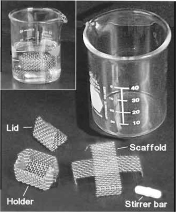
FIGURE 1 Accessories for CPD: specimen holder, lid for
holder, and scaffold are made from stainless steel mesh.
Inset shows an assembled set. - Locator grids (e.g., 7GC200, Ted Pella)
- Holders for critical point drying. We use a homemade holder (Fig. 1), which consists of a wire basket that fits the size of the critical point dryer's chamber. Such a design is good for correlative EM, as it is not very demanding to the shape and size of the coverslips. For noncorrelative EM, commercially available holders can be used (e.g., Cat. No. 8762 for coverslips under 7mm or Cat. No. 8766 for round 12- mm coverslips, Tousimis).
- 50-ml glass beakers
- Homemade scaffolds (Fig. 1)
- Stirrer bars (Fig. 1)
- Fine tip forceps
- Dissection microscope
- Critical point dryer. We use a semiautomatic Samdri-795 or manual Samdri PVT-3 (Tousimis). Other devices have also been used successfully. As a source of liquid CO2, we use high-quality carbon dioxide (Cat. No. CD 4.8SE, Praxair); however, lower quality grades can also be used if they have low water and carbohydrate contamination. The cylinder should be equipped with water and oil absorbing filter (Cat. No. 8781/82A, Tousimis).
- Vacuum evaporator. We use an Edwards 12E1 evaporator equipped with rotary and diffusion pumps, power supply, rotary stage, and thickness monitor (Cat. No. QM-311, Kronos, Inc.). Newer models with suitable configuration are now available from Edwards and other sources.

III. PROCEDURES
A. Cell Culture and Light Microscopy
Details of cell cultivation, introduction of fluorescent probes into cells, and light microscopic observation are beyond the scope of the present description. However, certain issues are specific to correlative microscopy and these we discuss.
1. Preparation of Locator Coverslips
Locator coverslips are helpful in facilitating the relocalization of the same cells. The reference marks on the coverslip should be recognizable by both light and EM. We use glass coverslips coated with a thin layer of gold through a locator grid (Fig. 2). Cells are selected within clear uncoated glass areas corresponding to the solid parts of the locator grid.
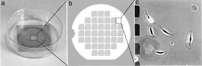 |
| FIGURE 2 Locator coverslip for relocalization of cells. (a) A 22 x 22-mm coverslip was coated with gold through the locator grid and mounted over the 18-mm hole in a 35-mm plastic dish with vacuum grease. (b) Diagram showing gold pattern on the coverslip. (c) Xenopus epidermal keratocytes growing on a coverslip with gold pattern. The imaged area corresponds to the box in b. Dark squares at left are gold islands corresponding to holes in the locator grid, which was used for shadowing. |
Steps
- Put one or two locator grids in the center of 22 x 22- mm glass coverslip. Place coverslips onto the stage of vacuum evaporator.
- Evaporate gold onto coverslips using a procedure suitable for the particular evaporator. Thickness of gold coating may vary. It should be clearly visible by eye as a purple transparent deposit. Avoid too thick of a coating because the gold may then contaminate the clear glass area under the grid.
- Remove grids, collect coverslips, and bake them at 160°C overnight. Baking prevents dislocation of gold grains by cultured cells.
2. Cultivation chambers
The locator coverslips may be mounted into different types of chambers suitable for cell cultivation and observation. For correlative microscopy, the chamber design should allow for the fast exchange of media. In our laboratory, we typically mount coverslips onto the hole in the bottom of 35-mm tissue culture dishes (Fig. 2) and perform light microscopic observations in open dishes. Compared to any kind of sealed chambers, this design allows faster processing for EM and decreases the lapse between light and EM observations. To prevent pH shift in the medium during observation, we use Leibovitz's L-15 medium.
Steps
- Smooth edges of the hole before mounting the coverslip.
- Apply a thin line of vacuum grease along the edges of the hole inside the dish. Use the minimum amount of grease required to prevent leakage to avoid complications during subsequent excision of the central area of the coverslip with the desired ceils (see later).
- Mount the coverslip with gold-coated side facing upward. Press firmly along the line of grease until grease forms a continuous clear circle around the hole without any air bubbles, which may cause leakage. Sterilize with UV irradiation before plating cells.
B. Preparation of Cytoskeletons
1. Extraction and Fixation
Solutions
- PEM buffer: 100mM PIPES, pH 6.9; 1 mM MgCl2; and 1 mM EGTA. To make 100 ml of 2x stock solution, mix ~70ml of distilled water and 6g of PIPES. While stirring, add concentrated KOH to this turbid solution until it almost clears. Add 76 mg of EGTA and 200 µl of 1M stock of MgCl2, adjust pH to 6.9 with 1N KOH, and complete with distilled water until 100ml. Store at 4°C.
- Extraction solution: 1% Triton X-100, 4% PEG in PEM buffer supplemented (optionally) with 2 µM taxol and/or 2 µM phalloidin. To make 10 ml, combine 5 ml of 2x PEM, 1 ml of 10% Triton X-100, 400mg PEG, and complete to 10ml with distilled water. Stir for ~10- 15min until dissolved. Store at 4°C and use within 1 week. Add 10µl of 2mM taxol (paclitaxel) in dimethyl sulfoxide (DMSO) or 10µl of 2mM phalloidin in DMSO before use.
- Sodium cacodylate stock: 0.2M Na-cacodylate, pH 7.3. Dissolve 4.28 g of Na-cacodylate in distilled water, adjust pH to 7.3 with HCl, and complete until 100ml. Store at 4°C.
- Glutaraldehyde: 2% glutaraldehyde in 0.1M sodium cacodylate, pH 7.3. To make 10ml, combine 5 ml of 0.2M Na-cacodylate, 0.8ml of 25% glutaraldehyde, and 4.2 ml of distilled water. Store at 4°C and use within a week.
- Tannic acid: 0.1% aqueous tannic acid. Weigh 10mg of tannic acid and dissolve in 10ml of distilled water. Use within a day.
- Uranyl acetate: 0.1% aqueous uranyl acetate. Weigh 10mg of uranyl acetate and dissolve in 10ml of distilled water. Remove undissolved salt by centrifugation. Store at room temperature.
Steps
- Using a pipette or vacuum aspirator, aspirate culture medium from a dish while it is on the microscope stage. Immediately, but gently, add prewarmed to 37°C. PBS with a wide-mouth pipette or pour from a beaker.
- Aspirate PBS and immediately add extraction solution at room temperature. Exchange of media should be fast to avoid cell damage by drying and to decrease the lapse between living and lysed state of the cell. Incubate for 3-5min at room temperature.
- Rinse cells with PEM buffer at room temperature two or three times, 1 min each.
- Add glutaraldehyde and incubate for at least 20 min at room temperature. If necessary, specimens can be refrigerated at this stage and stored for several days in sealed dishes to prevent drying. Before further processing, specimens should be brought back to the room temperature. If immunogold staining is required, it is best to do it after this step (see later).
- Remove glutaraldehyde and add tannic acid. No washing is necessary before application of tannic acid, although it is not contraindicated. Incubate for 20min at room temperature, rinse in three changes of distilled water, and incubate for 5min in the last change of water.
- Remove water and add uranyl acetate; incubate for 20 min at room temperature. Replace uranyl acetate with distilled water.
2. Immunostaining
Platinum replica EM is compatible with immunoelectron cytochemistry and with the use of colloidal gold as an electron-dense marker. The difference in electron density between colloidal gold particles and the platinum layer is sufficient for detection of the immune reaction in coated specimens. The specific protocol for immunogold EM depends on the primary antibody and its ability to recognize antigen under particular conditions. Initial evaluation of the quality of staining at the light microscopic level is strongly recommended. For most antibodies we use immunostaining after glutaraldehyde fixation because it provides the best structural preservation. We do not recommend using formaldehyde or methanol fixation, as they are generally inadequate for preserving structure at the EM level.
Solutions
- Sodium borohydrate NaBH4: 2mg/ml NaBH4 in PBS. Weigh 20mg of NaBH4 and complete with 10ml of PBS. Use immediately.
- Primary antibody: The required antibody concentration should be estimated in preliminary light microscopic experiments. For EM, use the antibody concentration that produces a bright immunofluorescence signal.
- Buffer A: 20mM Tris-HCl, pH 8.0, 0.5M NaCl, and 0.05% Tween 20. To make 100ml of 5x stock solution, dissolve 1.2g Trizma-HCl and 14.5g NaCl in distilled water. Adjust pH to 8.0. Add 250µl of Tween 20 and complete to 100ml with distilled water. Store at 4°C.
- Buffer A with 0.1% BSA: To make 50ml, combine 10ml of 5x stock buffer A, 50mg BSA, and 40ml of distilled water. Store at 4°C for 1 month.
- Buffer A with 1% BSA: To make 10ml, combine 2ml of 5x stock buffer A, 100mg BSA, and 8 ml of distilled water. Store at 4°C for 1 month.
- Secondary antibody: Colloidal gold-conjugated secondary antibody diluted 1:5 to 1:10 in buffer A with 1% BSA.
Steps
- After glutaraldehyde fixation (step 4 of Section III.B.1), wash specimens with PBS (two brief rinses and 5 min in the third change of PBS).
- Quench specimens by NaBH4 for 10min at room temperature. Shake off bubbles occasionally. Rinse in PBS (three changes, 5 min in the last change).
- Remove PBS from the dish. Using cotton swabs, wipe the buffer from the dish and coverslip, leaving wetness on only a small (approximately 5-7mm) central area containing the locator grid. However, be careful to avoid allowing this area to dry out. Apply primary antibody and incubate for 30-45 min at room temperature. Rinse in PBS (three changes, 5 min in the last change).
- Rinse once in buffer A with 0.1% BSA. Wipe coverslips as before and apply colloidal gold-conjugated antibody. Incubate overnight at room temperature in a sealed dish in moist conditions. Rinse in buffer A containing 0.1% BSA (three changes, 5min in the last change) and fix with glutaraldehyde, tannic acid, and uranyl acetate (steps 4-6 in the Section III.B.1) (Fig. 3).
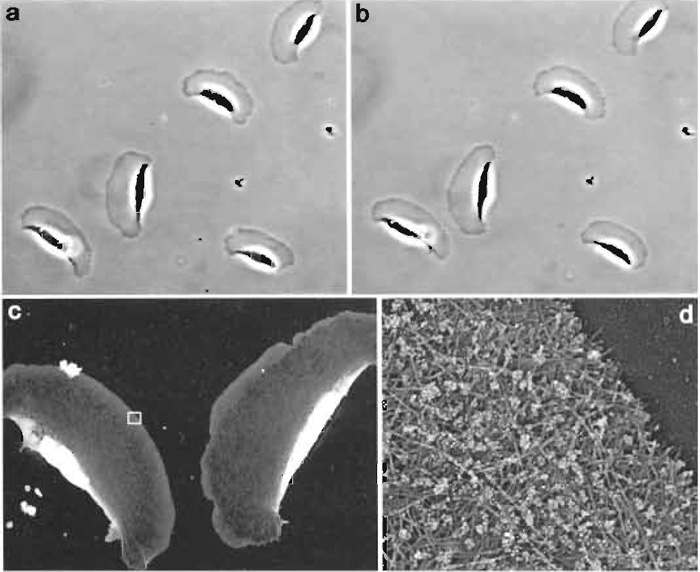 |
| FIGURE 3 Correlative immuno-EM of locomoting Xenopus keratocytes. The phase-contrast time-lapse sequence was acquired with 6-s intervals. The two phase-contrast images shown (a and b) were taken 1 min apart. After acquisition of the second image, cells were immediately extracted, fixed with glutaraldehyde, quenched with NaBH4, stained with rabbit antibody to Xenopus ADF/cofilin and secondary antibody conjugated with 10nm colloidal gold, and processed for platinum replica EM. Low-magnification EM (c) shows two keratocytes from lower left corner in b. Boxed region from c is enlarged in d. Gold particles appear as white dots because of the reversed contrast of the original image. Distribution of gold particles demonstrates that ADF/cofilin is excluded from the narrow zone at the extreme leading edge (Svitkina and Borisy, 1999). |
C. Critical Point Drying
The idea of the technique is to remove liquid from the sample without exposing it to high surface tension. This is accomplished by bringing the sample to or above the critical point, a specific combination of temperature and pressure for the particular liquid where phase boundary does not exist. For most liquids, including water, the critical point is too extreme to be of practical use. In contrast, carbon dioxide has a critical point at 31.3°C and 1072psi (72.9 atm) and represents the fluid of choice for CPD of biological samples. Because CO2 has limited solubility in water, ethanol (or acetone) is used as a transitional liquid, which is miscible with either water or CO2 in any proportion.
Solutions
- Graded ethanols: 10, 20, 40, 60, or 80% ethanol. Combine 10, 20, 40, 60, or 80ml of 100% ethanol, respectively, with distilled water until a final volume of 100ml. Allow to stand until all air bubbles are gone and temperature is equilibrated to ambient conditions.
- Uranyl acetate in ethanol: 0.1% uranyl acetate in 100% ethanol. Weigh 25 mg of uranyl acetate, add 25 ml of 100% ethanol, and stir until dissolved. Use within several hours.
- Dried ethanol: 100% ethanol dried over molecular sieves. Wash molecular sieves free of dust with multiple changes of water and bake overnight at 160°C. After cooling, combine 50-100 g of molecular sieves with 500ml of 100% ethanol. Seal with Parafilm. Store at room temperature for 2 days before use.
Steps
- If oil objectives are used for light microscopy, remove the immersion oil from the bottom of the coverslip with cotton swabs soaked in ethanol.
- Detach the coverslip from the bottom of a dish and quickly transfer it into a wide petri dish filled with water. Some silicone grease will remain on the lower side of the coverslip. Lightly press the coverslip down to the petri dish bottom, making sure that the grease does not contaminate the central area of the coverslip containing the cells of interest. Using a diamond pencil, cut off the greased edges of the coverslip to obtain a clean central part of the coverslip with the locator grid. It is helpful to use a razor blade as a guide for making cuts. Use a sharp diamond pencil and avoid glass crumbs around the cutting area to prevent coverslips from shattering. The optimal size of the central piece of the coverslip containing cells of interest is 6-8 mm.
- Place a specimen holder for CPD into a wide beaker filled with water. Cut lens tissue into pieces fitting the size of the holder. Put a sheet of lens tissue on the bottom of the holder and place the coverslip onto it. Load other coverslips one after another using additional lens tissue sheets as spacers. The lens tissue separates samples and helps retain a layer of liquid over the specimens during transfer. Keep the whole stack loose to allow for easy liquid exchange. Up to 12 coverslips with dimensions 6-8 mm may be processed simultaneously. Overloading the holder makes the exchange of liquid difficult. Loosely put on a lid to prevent the last sheet of lens tissue from flowing away.
- Put a stirrer bar into a 50-ml beaker. Place a wire scaffold over the stirrer. Add 10% ethanol in amount sufficient to cover the specimen holder when it is placed onto the scaffold. Quickly transfer the holder from water to the beaker (Fig. 1). Stir for 5 min.
- Prepare another beaker with 20% ethanol in the same way. Transfer the holder and stir for 5min. Repeat this step for 40, 60, 80, and twice for 100% ethanol. Two sets of beaker/stirrer bar/scaffold are sufficient for dehydration, as they can be alternated in successive steps.
- Place holder into uranyl acetate in ethanol and incubate for 20min. No stirring is necessary.
- Prepare beaker as in step 4 but with 100% ethanol, put in holder, and stir for 5 min. Repeat once more. Then, repeat twice with dried 100% ethanol.
- Fill the specimen chamber of the CPD device with dried 100% ethanol. The amount of ethanol in CPD chamber should be just enough to cover the holder. Place holder into the chamber. If the CPD device is equipped with a stirrer, put a stirrer bar underneath the holder. Close chamber and open CO2 cylinder and inlet valve on CPD machine. Cool down the chamber to 10-15°C to keep CO2 in liquid state. Maintain this temperature until the heating step. Turn stirrer on. Wait until the chamber is filled.
- Slightly open exhaust valve for 30 s, keeping inlet valve open to allow for exchange of ethanol to liquid CO2. If the CPD is not equipped with a stirrer, shake CPD manually during this step. Close exhaust valve. Repeat this washing step 10 times every 5min to remove all traces of ethanol. Keep the level of CO2 always above the upper edge of the holder.
- Turn off stirrer and cooler. Turn on heat to raise pressure and temperature above the critical point for CO2, usually until 40°C and 1200psi (80atm). Then slowly release pressure by opening exhaust valve. A fast decrease of pressure may cause condensation of CO2 back to liquid and ruin the dried samples.
- Remove holder from the CPD chamber and immediately place it in a sealed desiccated container. Dried cells can easily absorb moisture from air, which will introduce artifacts similar to those created by air drying. Therefore, it is important to keep samples inside the desiccator until ready for replica preparation.
D. Platinum Replica Preparation
1. Shadowing
Rotary shadowing at an angle creates a gradation of metal thickness depending on the 3D organization of the sample. Platinum is a popular metal for vacuum evaporation because it represents a reasonable compromise between melting temperature and grain size. Platinum grains deposited onto the specimen surface are not cohesive and can be distorted easily during subsequent manipulations or under the electron beam. The platinum layer should be stabilized by carbon, which forms a cohesive film and thus keeps platinum grains in place. The specific procedures for platinum and carbon shadowing depend on the particular device. Therefore, we describe just some important issues.
Mounting of Coverslips
Rotation of the stage will dislodge samples if they are not secured on the stage. Double-sided sticky tape is too strong and does not permit easy and safe detachment of samples, especially after being in vacuum. To make a mild mounting tape, sandwich double-sided tape between sticky parts of two Post-It notes so that the glued side of paper sheets is exposed. Cut off the unglued paper. To mount coverslips, attach a piece of this sandwich to the evaporator stage and attach coverslips. It is sufficient to attach just a corner or an edge of a coverslip to the paper. It is helpful to put marks on the paper to identify samples.
Platinum Shadowing
Source. Our system is set up to use platinum wire wrapped around tungsten wire as a source for shadowing. When voltage is applied, the tungsten wire heats up and the platinum melts and evaporates. Alternatively, platinum-carbon pellets can be used as a source. An advantage of pellets is that they produce finer grains.
Angle. Low angles from the source of platinum to the specimen stage provide high contrast, but reveal only the very top of the sample. High angles result in less contrast but allow for better visualization of the cell interior because of increased penetration of metal into deep hollows. We found a 45° angle to be most useful for whole mount cytoskeleton preparations, as it represents a reasonable compromise between contrast and penetration.
Thickness. Thicker coating reduces resolution but increases contrast and 3D range. In our experiments, a platinum layer thickness of 2.5-2.8 nm produces a fair balance between contrast and resolution. Thickness of the platinum layer can be monitored using a quartz crystal-based thickness monitor. If a thickness monitor is not available, approximate settings of the system may be established by a trial-and-error approach. In our system, 10mg of platinum wire completely evaporated from a distance of 100mm produced a layer of the required thickness.
Carbon Coating
Evaporate carbon at 90° with or without rotation to obtain a 2- to 3-nm-thick layer. The thickness of carbon is not very critical, as it is practically transparent to electrons. However, a layer thicker than 10nm becomes visible and interferes with the formation of image. Too thin a carbon layer may be insufficient for stabilization and result in crumbling of replicas after the removal of coverslips.
2. Mounting of Replicas on Grids
Platinum-carbon replicas of the cytoskeleton are released from the coverslip with hydrofluoric acid. If cell areas that are going to be studied are thin and have low electron density, such as lamella in spread cultured cells (Fig. 4), removal of glass is sufficient. For thick and electron-dense cell regions, organic components can be depleted with a strong oxidative agent, e.g., household bleach. For correlative microscopy, it is easier to select the area of interest while the replica is still attached to the coverslip. After drying and metal coating, cells have good contrast and are visible even under the dissection microscope.
Solutions
- Hydrofluoric acid: ~5% HF in water. Concentrated (49%) HF solution is supplied by the manufacturer in a plastic dispenser bottle. Work with HF in a fume hood, use plastic (not glass) dishes and pipettes, and wear gloves. Store in the fume hood. Prepare working solution in a 12-well dish (diameter 25 mm) before use. Drip several drops (~0.5-1.0ml) of concentrated HF from the dispenser bottle into a well. Add distilled water almost to the top.
- 0.01% Triton X-100: Take 10ml of distilled water and add 10µl of 10% Triton X-100. Store at room temperature not longer than 1 month.
- Clorox bleach (optional): Dilute in distilled water 1:2 to 1:10 depending on the strength of bleach.
Steps
- Using mild double-sided tape (see earlier discussion), immobilize a platinum-carbon-coated coverslip on the bottom of a wide petri dish with cell side up, leaving a region of interest unobstructed.
- Under the dissection microscope, localize cells of interests using the gold pattern. Make cuts with any sharp tool (razor blade or needle) in the platinumcarbon layer around cells of interest. Continue the cuts up to the edges of the coverslip to facilitate release of the selected area from the rest of the replica.
- Float a coverslip with cell side up onto the surface of the HF in a well. In minutes the coverslip falls down, leaving the replica floating. After separation of the coverslip, the replica falls apart along the introduced cuts. The pattern of the gold shadowing on the resulting pieces helps identify the desired replica fragments.
- Fill another well with distilled water (~5ml). Add ~2µl of 0.01% Triton X-100. Using a platinum loop, transfer replica pieces onto the surface of water. Traces of detergent in the water prevent the replica from breaking apart, which usually happens because of a large difference in surface tension between HF and water. An overdose of detergent, however, can result in shrinkage and drowning of replicas. Wait 1 min or more.
- Fill a well with distilled water. Transfer replica
pieces onto the surface of pure distilled water. Wait
1 min or more. For electron-dense specimens, go
through additional steps:
- Fill a well with diluted household bleach and transfer replica pieces onto its surface. Wait 2 to 20min depending on the cell type and the strength of the bleach.
- Fill another well with distilled water. Transfer replica pieces onto the surface of pure distilled water. Wait 1 min or more. Repeat the step once more.
Note: Depletion of organic material by bleach is not compatible with immunogold labelling, as it causes the degradation of antibody associated with colloidal gold particles and consequent elimination of gold label from replicas. - Mount replica pieces onto Formvar-coated EM grids with lower side of the replica to the Formar film. Use low mesh or single slot grids to reduce the chance of getting the region of interest onto a grid bar. Control under the dissection microscope is helpful for the targeted mounting of replicas on grids.
- Examine samples in TEM. (Fig. 4) Present images in inverse contrast (as negatives) because it gives a more natural view of the structure, as if illuminated with scattered light.
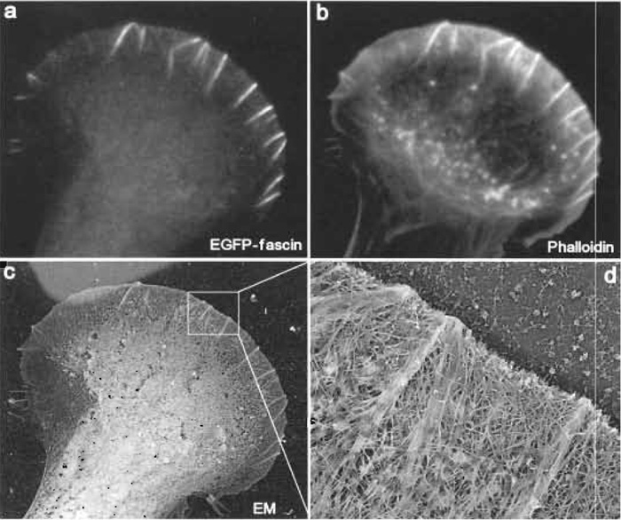 |
| FIGURE 4 Correlative fluorescence and EM of mouse melanoma B16F1 cells. The cell shown was transiently transfected with EGFP-fascin (a) and, after extraction and fixation, stained with Texas red phalloidin (b). After EM processing, the same cell was identified at low magnification (c). Lighter background at the upper left corner is due to gold evaporation through a hole of the locator grid. (d) High-magnification view shows actin filament organization in the leading lamellipodium. Several microspikes within lamellipodium, which are enriched in fascin (see a), have actin filaments organized into tight bundles, whereas lamellipodium between microspikes, which is depleted in fascin, has actin filaments organized into the dendritic network. |
IV. PITFALLS
- Cytoskeletal elements look distorted. Most likely, extraction was not performed gently enough. Explore different extraction conditions comparing living and extracted cell images.
- Cytoskeletal elements look fragmented. One possible reason is inadequate fixation. Check your reagents for fixation capacity. Another possibility is photodamage or phototoxicity during live cell imaging. Decrease light and/or exposure and close field diaphragm as much as possible to the area of interest during sequence acquisition.
- Cytoskeletal elements look flattened and fused with each other. This is an artifact introduced by surface tension (Ris, 1985). To avoid this problem, always keep a layer of liquid over the specimens when they are transferred from one solution to another. The problem may also occur because of incomplete replacement of water to ethanol or ethanol to liquid CO2 during dehydration and CPD. Any remaining traces of ethanol or water dry out below their critical points after CPD and ruin the structure. Another possible reason is high ambient humidity. Dried samples are highly hygroscopic. They may absorb moisture from air, which will subsequently dry below the critical point. Loading the evaporator is a step when samples are most susceptible to humidification, as it takes some time to get coverslips from the CPD holder and mount them onto the evaporator stage. Keep humidity in the room as low as possible. In our experience, it is sufficient to keep it under 50%. Also, prepare evaporator for coating in advance, before getting samples from the desiccator.
References
Lindroth, M., Bell, P. B., Jr., et al., (1992). Preservation and visualization of molecular structure in detergent-extracted whole mounts of cultured cells. Microsc. Res. Tech. 22, 130-150.
Ris, H. (1985). The cytoplasmic filament system in critical pointdried whole mounts and plastic-embedded sections. J. Cell Biol. 100, 1474-1487.
Svitkina, T. M., and Borisy, G. G. (1998). Correlative light and electron microscopy of the cytoskeleton of cultured cells. Methods Enzymol. 298, 570-592.
Svitkina, T. M., and Borisy, G. G. (1999). Arp2/3 complex and actin depolymerizing factor/cofilin in dendritic organization and treadmilling of actin filament array in lamellipodia. J. Cell Biol. 145, 1009-1026.
Svitkina, T. M., Verkhovsky, A. B., et al., (1995). Improved procedures for electron microscopic visualization of the cytoskeleton of cultured cells. J. Struct. Biol. 115, 290-303.
Svitkina, T. M., Verkhovsky, A. B., et al., (1997). Analysis of the actinmyosin II system in fish epidermal keratocytes: Mechanism of cell body translocation. J. Cell Biol. 139, 397-415.
Support our developers


