Freeze Fracture and Freeze Etching
I. PRINCIPLES OF FREEZEFRACTURE TECHNIQUE
The technique of freeze fracture is unique among electron microscopic (EM) methods in that it gives en face views of the internal organisation of biological membranes, allowing the study of the in-plane distribution of integral proteins spanning the lipid bilayer and of other membrane features, as a function of developmental stage, experimental conditions, or onset of disease. Although freeze fracture can be undertaken using very simple equipment that can be constructed in any workshop, in conjunction with a standard vacuum coating unit (Bullivant and Ames, 1966; Bullivant et al., 1979), or using a commercial attachment to such a coating unit, it is normally performed within a specialized high vacuum freeze-fracture apparatus, with a temperature-controlled, liquid nitrogen-cooled holder for specimens. The standard procedure for specimen preparation by freeze fracture in such an apparatus is summarised in Fig. 1 and can be described briefly as follows.
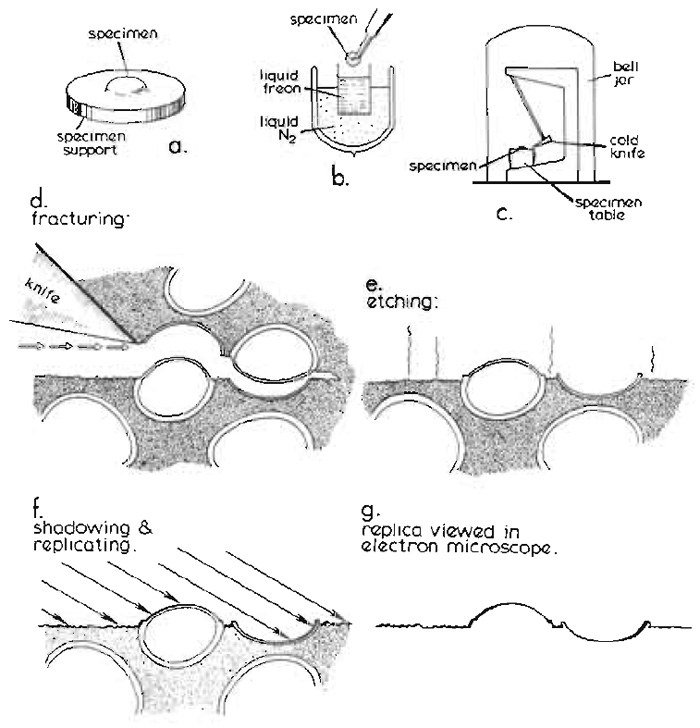 |
| FIGURE 1 Basic steps in the conventional freeze-fracture procedure described in the text. Diagram courtesy of Daniel Branton, first published by Shotton (1982), reproduced by permission. |
A. Freezing
Conventionally, a small block of biological tissue (approximately 2 × 2 × 1 mm) or a droplet of cell suspension on a copper or gold support (Fig. 1a), stabilised by glutaraldehyde fixation and cryoprotected by infiltration with 25-30% glycerol, is first rapidly frozen by plunging it manually into nitrogen slush or a liquified cryogen cooled to near its freezing point by liquid nitrogen (Fig. 1b). Full details of specimen supports and alternative rapid freezing methods are found in the article by Severs and Shotton and in Severs et al. (1995).
B. Fracturing
After storage for an unlimited period in liquid nitrogen, the frozen specimen is transferred quickly to the precooled, temperature-controlled specimen table within the high vacuum chamber of a freeze-fracture apparatus, either via an airlock or, more usually, after venting the chamber with dry nitrogen gas, which is then reevacuated to better than 2 × 10⁻⁶mbar (Fig. 1c) (1mbar = 100pa = 0.75 torr). Freeze fracture is traditionally achieved by striking the specimen, maintained at -110°C, with a cold razor blade clamped within the jaws of the hollow microtome knife blade holder, which is itself filled and cooled to below -150°C with circulating liquid nitrogen. As when a log of wood is cleaved by an axe, a plane of free fracture precedes the blade edge, following a line of least resistance through the frozen specimen (Fig. 1d). When this fracture plane encounters a cell, it frequently passes along the centre of the lipid bilayer of the plasma membrane, as this is a line of weakness at cryogenic temperatures, splitting the asymmetric membrane into an extracellular (E) half and a protoplasmic (P) half (nomenclature of Branton et al., 1975). Integral proteins, which span the membrane, may partition with one or other half of the membrane, from which they will protrude to form small freeze-fracture intramembrane particles (IMPs), leaving complementary pits in the other half membrane from which they were wrenched. Internal cell membranes may be similarly fractured, if the fracture plane initially passes through the plasma membrane and into the cell. Alternative specimen supports, including "double replica" specimen holders that provide tensile fracture of the frozen specimen, are detailed in the article by Severs and Shotton.
C. Etching
The specimen may then optionally be etched after fracturing (Fig. 1e). During etching, water molecules are allowed to sublime from the frozen surface of the fractured specimen, which for this purpose is fractured at a slightly higher temperature, at which the sublimation pressure of ice exceeds the partial pressure of the residual water molecules in the vacuum atmosphere by about 10-fold (typically -100°C for a vacuum of 2 × 10⁻⁶mbar), leading to an etching rate of about 2nm per second. The sublimed water molecules are condensed on a nearby cold trap, typically the underside of the cooled knife, which is positioned for this purpose above the fractured specimen. Etching lowers the specimen ice table and exposes the true surfaces of freeze-fractured membranes, thereby revealing membrane surface features of interest that were obscured previously by the overlying ice. The introduction of ultrarapid freezing techniques (see previous article by Severs and Shotton) has made it possible to freeze a wide variety of living tissue sufficiently rapidly to achieve good cryofixation of the surface layer of cells in the absence of chemical fixation and glycerol cryoprotection, enabling their subsequent etching. More extensive etching for up to 30min at -100°C (deep etching or freeze drying) may be used to reveal more extensive cytoskeletal, extracellular, or membrane features or macromolecular structure (see Heuser, 1989; Hawes and Martin, 1995; and chapters in Severs and Shotton, 1995).
D. Replication
The frozen surface of a freeze-fractured or freezeetched specimen is rich in topographical detail, but is extremely labile. In order to convert this labile structural information into stable contrast information accessible in the electron microscope, the specimen is obliquely shadowed with a thin layer of atomic platinum (typically with an average thickness of 1.5 to 2nm), deposited from an evaporative source, usually an electron bombardment gun (Fig. 1f). The platinum atoms landing upon the frozen surface of the replica do not form a homogeneous layer, even upon smooth surfaces. Instead, after travelling short distances laterally on the membrane surface as they lose kinetic energy, the atoms coalesce to form small platinum grains, about 1 nm in diameter, leaving the immediately adjacent surface free from platinum. The deposited film contains 5% (w/w) carbon with the platinum, which limits the maximum size of the grains to about 1.5 nm. These frequently form upon existing surface particles, giving a "decoration" effect, which may accentuate specimen detail in a useful way. The presence of these grains effectively limits the resolution of the replica to approximately 2.5 nm.
Alternative shadowing materials may be used, most commonly a mixture of tantalum and tungsten (approximate stoichiometry 80:20, w/w), which provides replicas of somewhat smaller grain size and higher resolution. However, such replicas are hard to make reproducibly, as the composition of the tantalum- tungsten anode of the electron bombardment gun changes from one evaporative shadowing run to the next due to the higher vapour pressure of the molten tantalum. The replicas are also of much lower contrast and have more limited chemical stability than conventional platinum replicas, and hence their use is confined almost exclusively to high-resolution ultrastructural studies (e.g., Abermann et al., 1972; Zingsheim and Plattner, 1976; Gross, 1987).
With conventional unidirectional platinum shadowing of stationary specimens, the platinum atoms accumulate on the near side of protrusions, leaving platinum-free "shadows" in their lee. Alternatively, the specimen may be rotated during replication while maintaining the platinum deposition angle constant relative to the plane of fracture. Such rotary shadowing, which results in a uniform distribution of platinum grains around protrusions and an absence of shadows, is particularly useful for deep etched specimens. In either case, this discontinuous and physically fragile platinum surface replica is then strengthened by a uniform backing of electron-translucent carbon (about 15 to 20nm thick; not shown in Fig. 1), deposited either unidirectionally from above or, for additional strength, from an angle of 80° while the specimen is rotating. This combined platinum-carbon replica is then removed from the vacuum chamber, is cleaned free of all the original biological material by digestion of the underlying thawed specimen with bleach or chromic acid followed by washing with distilled water, and is viewed directly in the transmission electron microscope (Fig. 1g).
II. TECHNICAL ADVICE
Precise details of the operation of the freeze-fracture apparatus, replication conditions, gun adjustments, and so on will vary between different models of freezefracture apparatus and should be conducted according to the manufacturers' instructions. Detailed comparative descriptions of different types of freeze-fracture equipment are given by Newman (1995). The following advice, based on experience with the Balzers BAF 300 machine, should be of general applicability.
A. Before the Freeze.Fracture Run
Check that there is enough liquid nitrogen to complete the run and prepare the electron bombardment guns for use according to the manufacturer's instructions. Check the incident shadowing angle of the platinum gun, changing it if necessary. The normal angle of incidence for unidirectional platinum shadowing of freeze-fracture replicas is 45°; from 6° to 26° is most useful for rotary shadowing of deep-etched specimens, depending upon the nature of the specimen; and 9° and 6° are used for unidirectional and rotary low-angle shadowing, respectively, of individual macromolecules absorbed onto mica sheets. For microtome fracture, fit an appropriate specimen stage and a reusable tungsten blade or a new single-edged carbon steel razor blade. Do not use stainless steel razor blades, as their edges bend on contact with ice and thus do not fracture well. Using a binocular dissecting microscope, ensure that the blade is horizontal above the specimen positions. Alternatively, fit a double-replica opening device in place of the blade and an appropriate doublereplica specimen stage. Good thermal contacts should be ensured by the use of small amounts of a thermal conductive paste or high vacuum grease. If appropriate for your machine, prepare and fit a "shadow paper" (a piece of thin card with a central cutout, placed as a collar around the specimen stage where it will intercept some of the evaporated material), which will provide a permanent record of the replication run, to supplement any chart recorder trace made of the stage temperature and quartz crystal replica thickness monitor output.
B. Precooling the Stage and Specimen Preparation
Close and evacuate the chamber. Turn on the quartz crystal replica thickness monitor to warm up. At a vacuum of 10-4mbar or better, turn on the chart recorder (if used), start the stage cooling, and briefly test fire both guns. Under liquid nitrogen, mount the specimen supports bearing the frozen specimens in the appropriate specimen holder in preparation for transfer to the specimen stage of the apparatus.
C. Loading Specimens
After the stage has been allowed to equilibrate at its minimum temperature (below -170°C) for 5 min, turn off the high vacuum gauge, vent the chamber with dry nitrogen gas (conveniently generated by running liquid nitrogen through a length of uninsulated copper tubing) in order to prevent the water vapour contamination that would otherwise occur if venting with air, open the chamber door or specimen access port, quickly transfer the specimens from liquid nitrogen to the cold specimen table, close the chamber, and immediately reevacuate. Modern freeze-fracture machines are often equipped with an airlock so that specimens may alternatively be loaded directly into the chamber without breaking the vacuum.
D. Specimen Temperature Adjustment
At a vacuum of 10-4mbar or better, start the knife cooling and raise the specimen temperature to -110°C (for freeze fracture) or -100°C (for freeze etching). For the standard specimen stage, the indicated temperature and the actual stage temperature should correspond fairly exactly. However, the poor thermal contacts that may occur when using certain designs of double-replica specimen holders mean that the specimens may in practice be 5 to 15° warmer than indicated so that the indicated specimen stage temperature must be set low to compensate. One should predetermine these temperatures, etching rates, and contamination conditions using test specimens such as erythrocyte ghosts frozen in distilled water (ghost preparation is described by Shotton, 1998) and/or a digital thermometer with the thermocouple clamped in place of one of the specimens for direct measurements. Note that the specimens may take 10min to reach temperature equilibrium after a large change in temperature and 5min to reach equilibrium after a small (<10°C) change.
E. Fracture Process
When fracturing with a microtome blade, observe the specimens with the binocular microscope and use the microtome controls to lower the knife blade until it is just clear of the tops of the specimens. Then make a series of progressively lower passes of the blade over the specimens. If possible, it is preferable to make the actual cuts slowly by hand rather than using the motor drive, thus enabling one to get a feel of the blade passing through the ice of the specimens. Reduce the cutting depth to a minimum as soon as any appreciable area of specimen is being cut and continue cutting until all specimens show large smooth fractured areas. For elongated cells such as nerve and muscle fibres, extensive fracture planes are best obtained by orienting the specimens so that the fibres are parallel with the edge of the blade and by cutting fast by motor using only a few deep cuts. When using a doublereplica device, fracturing is a single event that should be done after temperature equilibration and preparation for shadowing.
Prior to the final cut (or to fracture in the doublereplica device), check the specimen temperature, ensure that the vacuum is better than 2 × 10⁻⁶mbar, and prepare for shadowing. (Modern freeze-fracture machines may achieve vacuum of 2 × 10⁻⁷mbar or better.) Then make the final cut, check through the binoculars that the specimen surfaces are clear of debris, and either shadow immediately or reverse the knife over the specimens to act as a cold trap while etching.
F. Etching
Normally, etching is conducted immediately after fracture at -100°C for 60s in a vacuum of better than 2 × 10⁻⁶ mbar, with a cold trap (below -160°C in close proximity to the specimen surfaces. This lowers the ice level approximately 120nm. Deep etching, used, for example, to expose macromolecules adsorbed to the surfaces of mica flakes or to reveal the cytoskeleton of permeabilized cells, is performed for longer, at a higher temperature
(-95°C), or both. If taken to completion, this is equivalent to freeze drying.
G. Replication
A quartz crystal replica thickness (thin film) monitor, positioned adjacent to the specimen stage in the path of the shadowing beams, is usually used to monitor replica deposition rates and amounts. Sequentially, operate the platinum and carbon guns according to the manufacturer's instructions to deposit the desired thickness of material, with the specimen stage stationary or rotating, as required. It is usual for unidirectional shadowing to deposit 1.5 to 2 nm thickness of a 95% Pt- 5% C mixture from the platinum gun. The amount of platinum deposited is critical and should not be more than the minimum required to generate good contrast. It is best to deposit the platinum at as rapid a rate as possible, starting to fire the platinum gun immediately prior to moving the knife away from its position over the specimens or just before opening a double-replica device, thus immediately exposing the specimens to a stream of platinum vapour, reducing to a minimum the time during which contamination might occur.
Immediately after platinum shadowing, strengthen the replica with a 10- to 20-nm-thick layer of carbon from the carbon gun. Quite large differences in the amount of carbon deposited make little obvious difference to the final appearance of the replica, except in the case of deep-etched filamentous structures, where too much carbon creates a large semitransparent "ghost" replica surrounding the thin carbon replica. However, for maximum contrast, the carbon thickness should be kept to the minimum required to maintain the structural integrity of large replica fragments during the subsequent cleaning process. During the carbon deposition, heating of the crystal by radiation from the carbon gun, which has a larger anode and uses a higher electron bombardment current, is significant and will lead artifactually to a competing increase in the crystal frequency, which is "recovered" after the carbon evaporation ceases. Once this behaviour is recognised, it can be accommodated for easily by starting the carbon shadowing as a small positive beat frequency. On initial heating the beat frequency will drop. It will then rise to a predetermined cutoff point as carbon is deposited and will finally "overshoot" by an amount equal to the initial drop as the crystal cools at the end of the carbon deposition.
Rotary shadowing is conducted as for unidirectional shadowing except that a commutator unit is used to rotate the specimen about an axis perpendicular to the fracture plane during both platinum and carbon deposition. A little over half the amount of platinum normally used for unidirectional shadowing is usually sufficient to give good contrast for rotary-shadowed freeze-etch replicas, with the normal amount of carbon.
After carbon shadowing, return all gun controls to zero, switch off the high tension supply, the monitor and recorder, the knife cooling and the high vacuum gauge, and prepare to remove the specimens. Stage cooling may be continued until the specimens have been removed.
H. Specimen Removal and Apparatus Shutdown
Vent the chamber and remove the specimens, minimising frosting on the specimens after venting by working fast. Then treat the specimens for replica removal as described later. Only when this has been done, shut down the apparatus. Turn off the stage cooling and reevacuate the chamber. If appropriate, turn on the stage and knife heating. When both are warm, revent the chamber, safely discard the disposable razor blade (if used), remove any water condensation droplets from the stage or microtome with paper tissues, and complete the drying process with a hot air gun. Finally, close the chamber and reevacuate. If appropriate, raise the knife to its upper limit, ready for the next run. When the vacuum is better than 10-5mbar, the pumping unit may be turned off, following the manufacturer's instructions. Complete the run record log sheet.
I. Retrieval and Cleaning of Replicas
Replica cleaning is often the most difficult stage of the entire procedure, during which replica fragmentation is frequently experienced. All dishes, implements, and solutions must be scrupulously clean to avoid replica contamination.
For replicas of cell suspensions, hold the specimen support above or just in contact with the surface of clean distilled water in a white ceramic spotting tray or a small petri dish, wait for it to thaw and the frost on top of the replica to evaporate, and then slowly immerse the specimen support into the water at approximately a 30° angle to the horizontal. The hydrophobic replica of the fractured surface will float off intact onto the water surface, surrounded by junk from the surrounding nonfractured (and hence rough) surfaces of the specimen, from which it may be separated easily. Transfer the floating replica (without any of the surrounding junk) onto the surface of a solution of sodium hypochlorite [technical grade, 10-14% (w/v) available chlorine] diluted to 50% with 10mM sodium hydroxide, and leave covered at room temperature for at least 30min (or overnight). (Commercial bleach should only be used if free from detergents, which tend to wet the replica and cause it to sink.) Then rinse the cleaned replica by transferring it sequentially onto two changes of distilled water and finally mount on an EM grid. Replica fragmentation upon transferring to and from cleaning solution is minimised if the replica is picked up on the upper surface of a bent round-ended glass rod formed using a Bunsen flame or the bent sealed tip of a Pasteur pipette formed in the flame of a small alcohol lamp to resemble an ice-hockey stick in shape. This method transfers less liquid than the use of a platinum loop, and any violent mixing of cleaning solution and water occurs at the underside of the rod while the replica is still safe on the upper surface. More thorough replica cleaning may be achieved, if necessary, by acidifying the hypochlorite with concentrated hydrochloric acid to form a stronger oxidising solution, by warming the hypochlorite to 60°C, or by using chromic acid. Concentrated sulphuric acid alone will digest the cellulose of plant specimens. Replicas of deep-etched, rotaryreplicated specimens are among the most difficult to clean, having a layer of platinum-carbon almost totally enveloping many of the biological structures, and prolonged exposure to strong acids may be required to achieve complete cleaning. Swelling of enclosed structures during this cleaning process can lead to severe replica fragmentation, but even the smallest of visible replica fragments can hold valuable structural information and so should all be kept, washed, and mounted on formvar-coated grids (see Section II,J). Other methods of cleaning replicas of difficult specimens are described in Shotton (1998b).
J. Mounting of Replicas
Floating replicas may be picked up from the meniscus of distilled water on bare EM grids either from above or from below. In the latter case, the EM grids should first be made hydrophilic by glow discharge, by brief immersion in a 0.1-mg/ml bacitracin solution, or by washing in alcoholic sodium hydroxide (30g NaOH dissolved in 30ml distilled H2O, added to 250ml 98% EtOH) followed by vigorous agitation in two changes of distilled water. Replicas are then mounted by careful manipulation of the submerged grid below the replica fragment, followed by slow withdrawal of the grid through the water surface. If, during this withdrawal, the grid is rotated to be at ~90° to the meniscus, with the replica fragment centrally located on it, little water will accompany removal of the grid. This can subsequently be removed by gently blotting the back of the grid onto a circle of filter paper and then by drying between the tips of the forceps holding the grid with a pointed piece of the filter paper, before placing the grid box. If the replica is to be picked up from above, the EM grid should be brought down flat onto the replica and then removed with a twist of the wrist to rotate it upside down at the meniscus, with partial submersion to ensure good adhesion of the replica with the grid. For certain investigations, it is important to know the orientation of the replica and hence the handedness of its projected image. For this, one should adopt a convention of always mounting replicas in the same orientation on one of the surfaces of the EM grid (either the dull or the shiny surface) and of orienting this surface facing to the right in one's grid storage box.
Bare 400 mesh hexagonal thin-bar EM grids are ideal for observing replicas of cell suspensions, but do not allow uninterrupted observation of extensive fracture faces of long myotubes or other large cells. For such replicas, formvar-coated 150-mesh or slot EM grids may be used, which have been coated lightly with carbon on their reverse side (i.e., on the side of the grid bars not covered with formvar, as opposed to the conventional method of depositing the carbon on top of the formvar layer, out of contact with the metal grid itself). This has the advantage that the flat surface of the formvar film remains hydrophilic and can be used to pick up floating replicas from below with ease.
Replicas should be observed at an intermediate magnification (×20,000-×90,000) in a transmission electron microscope and should appear crisp, clean, and of high contrast (Fig. 2). More in-depth descriptions of the technique, of the interpretation of freeze-fracture images, and of the potential artefacts that accompany the freeze-fracture technique, involving variations in replica quality, etching artifacts, specimen contamination, and plastic distortion, are discussed more fully in the longer original edition of this article in Shotton (1998b) and in earlier publications by Fisher and Branton (1974), Southworth et al. (1975), Sleytr and Robards (1977), Rash and Hudson (1979), Robards and Sleytr (1985), Abysekera and Robards (1995), and Shotton and Severs (1995).
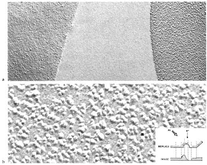 |
| FIGURE 2 Freeze-fracture replica showing the appearance of erythrocyte fracture faces and intramembrane
particles. (a) On the right, the protoplasmic fracture face (P face), and on the left, the extracellular fracture
face (E face) of normal erythrocyte ghost membranes from two adjacent cells separated by a region of ice. Positive contrast image with the platinum shadowing direction from below. Magnification ×67,200 (b) An erythrocyte P face shown at a higher magnification to reveal individual intramembrane particles (IMPs), which throw short white shadows upward. Magnification ×255,000. (Inset) Diagrammatic view of a single platinum-replicated IMP and of its projected electron scattering power, which determines the optical density of its positive photographic image when viewed with the electron beam normal to the replica. From Steere and Rash (1979), reproduced by permission of Raven Press. |
References
Abermann, R., Salpeter, M. M., and Bachman, L. (1972). High resolution shadowing. In "Principles and Techniques of Electron Microscopy" (M. A. Hudson, ed.), pp. 197-217. Van Nostrand Reinhold, New York.
Abeysekera, R. M., and Robards, A. W. (1995). Freeze-fracture artifacts: How to recognise and avoid them. In "Rapid Freezing, Freeze Fracture and Deep Etching" (N. J. Severs and D. M. Shotton, eds.), pp. 69-88. Wiley-Liss, New York.
Branton, D., Bullivant, S., Gilula, N. B., Karnovsky, M. J., Moor, H., Mühlethaler, K., Northcote, D. H., Packer, L., Satir, B., Satir, P., Speth, V., Staehlin, L. A., Steere, R. L., and Weinstein, R. S. (1975). Freeze-etch nomenclature. Science 190, 54-56.
Bullivant, S., and Ames, A. (1966). A simple freeze-fracture replication method for electron microscopy. J. Cell Biol. 29, 435-447.
Bullivant, S., Metcalfe, P., and Warne, K. P. (1979). Fine structure of yeast plasma membrane after freeze fracturing in a simple shielded device. In "Freeze Fracture: Methods, Artifacts and Interpretations" (J. E. Rash and C. S. Hudson, eds.), pp. 141-147. Raven Press, New York.
Fisher, K., and Branton, D. (1974). Application of the freeze-fracture technique to natural membranes. Methods Enzymol. 32, 35-44.
Gross, H. (1987). High resolution metal replication of freeze-dried specimens. In "Cryotechniques in Biological Electron Microscop" (R. A. Steinbrecht and K. Zierold, eds.), pp. 205-215. Springer- Verlag, Berlin.
Newman, T. M. (1995). A guide to equipment for production of freeze-fracture replicas. In "Rapid Freezing, Freeze Fracture and Deep Etching" (N. J. Severs and D. M. Shotton, eds.), pp. 51-68. Wiley Liss, New York.
Rash, J. E., and Hudson, C. S. (1979). "Freeze Fracture: Methods, Artifacts and Interpretations." Raven Press, New York.
Robards, A. W., and Sleytr, U. B. (1985). Low temperature methods in biological electron microscopy. In "Practical Methods in Electron Microscopy" (A. M. Glauert, ed.), Vol. 10. Elsevier, Amsterdam.
Severs, N. J., Newman, T. M., and Shotton, D. M. (1995). A practical introduction to rapid freezing techniques. In "Rapid Freezing, Freeze Fracture and Deep Etching" (N. J. Severs and D. M. Shotton, eds.), pp. 31-50. Wiley-Liss, New York.
Severs, N. J., and Shotton, D. M. (1995). "Rapid Freezing, Freeze Fracture and Deep Etching." Wiley-Liss, New York.
Shotton, D. M. (1998a). Preparation of human erythrocyte ghosts. In "Cell Biology: A Laboratory Handbook" (J. E. Celis, ed.), 2nd Ed. Vol. 2, pp. 26-33. Academic Press, San Diego.
Shotton, D. M. (1998b). Freeze fracture and freeze etching. In "Cell Biology: A Laboratory Handbook" (J. E. Celis, ed.), 2nd Ed., Vol. 3, pp. 310-322. Academic Press, San Diego.
Shotton, D. M., and Severs, N. J. (1995). An introduction to freeze fracture and deep etching. In "Rapid Freezing, Freeze Fracture and Deep Etching" (N. J. Severs and D. M. Shotton, eds.), pp. 1-30. Wiley-Liss, New York.
Sleytr, U. B., and Robards, A. W. (1977). Freeze fracturing: A review of methods and results. J. Microsc. 111, 77-100.
Southworth, D., Fisher, K., and Branton, D. (1975). Principles of freeze fracturing and etching. In "Techniques of Biochemical and Biophysical Morphology" (D. Glick and R. Rosenbaum, eds.), Vol. 2, pp. 247-282. Wiley, New York.
Steere, R. L., and Rash, J. E. (1979). Use of double-tilt device (goniometer) to obtain optimum contrast in freeze-fracture replicas. In "Freeze Fracture: Methods, Artifacts and Interpretations" (J. E. Rash and C. S. Hudson, eds.). Raven Press, New York.
Zingsheim, H. P., and Plattner, H. (1976). Electron microscopic methods in membrane biology. In "Methods in Membrane Biology" (E. D. Korn, ed.), Vol. 7, pp. 1-146. Plenum Press, New York.
Support our developers


