Laser Capture Microdissection
Laser capture microdissection (LCM) is a technology for procuring pure cell populations from a heterogeneous tissue or cytological preparation under direct microscopic visualization. One of the most common problems encountered by the investigator involved in the proteomic or genetic analysis of tissue samples arises from the heterogeneous nature of the tissue and the need for a pure cell population for studies. There are often many cell populations in a single tissue. When working with malignant or premalignant tissues, the abnormal cells of interest may lie within, or very close to, areas of totally normal cells.
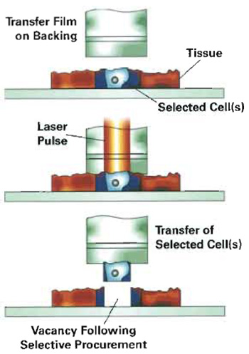 |
| FIGURE 1 A polymer film is placed in direct contact with the tissue. A pulsed infrared laser melts the polymer, allowing the polymer to surround and embed the cells in the vicinity of the laser pulse. The polymer-cell composite is removed from the tissue section, resulting in microdissection of the cells. |
LCM enables the investigator to isolate single cells or multiple cells, representing specific malignant, premalignant, or normal tissues. The ability to analyze pure cell populations permits analysis of molecular events representative of the tissue at the time of sample procurement. Comparisons of molecular events at tissue interfaces may be analyzed in relation to the microtumor environment using LCM technology. The isolated cells may be assayed for DNA, RNA, or protein by any method with sufficient sensitivity.
A stained section of the heterogeneous tissue is mounted on a glass microscope slide and viewed under high magnification. The slide position is manipulated via a joystick, allowing visualization of the cells for microdissection. Cells of interest are directed under an infrared (IR) laser, mounted in the optical axis of the microscope. A thermoplastic film, placed in direct contact with the tissue section, is melted with a laser pulse. The molten polymer surrounds and embeds the cells in the vicinity of the laser pulse, forming a polymer-cell composite. When the film is lifted away from the tissue, the cells of interest are sheared from the tissue section and remain adhered to the polymer. Incorporation of an energy-absorbing dye into the thermoplastic film, coupled with the low energy of the IR laser, prevents damage to the cellular constituents. Extraction buffers are applied to the film for solubilization of DNA, RNA or protein contained in the captured cells (Fig. 1).
Automated LCM (AutoPix, Arcturus Bioscience, Mountain View, CA) combines the features of LCM, robotics, and imaging software to facilitate the visualization and microdissection of tissue. Quantitation of the laser spot size and percentage overlap of the laser pulses add a level of standardization to the microdissection technology. Cell recognition software enhances LCM technology for fluorescent immunostained tissues.
The AutoPix makes it possible for the operator to conduct "hands off" microdissection once the relevant cells are marked by the operator or are recognized by the computer image recognition software.
A. Specimen
- For protein analysis of microdissected tissue, use frozen tissue sections cut at 2-15µm or cytospin preparations.
- For RNA or DNA analysis of microdissected tissue, use frozen tissue sections cut at 2-15µm, cytospin preparations, or ethanol or formalin-fixed paraffin-embedded tissue sections.
- Precleaned, uncoated glass microscope slides (Cat. No. G15978A, A. Daigger & Co.)
- Hematoxylin and eosin (H&E) stain:
- Mayer's hematoxylin solution (Cat. No. MHS- 128, Sigma Diagnostics)
- Hematoxylin is an inhalation and contact hazard. Wear gloves when handling.
- Eosin Y solution, alcoholic (Cat. No. HTl101- 128, Sigma Diagnostics)
- Eosin Y is flammable. Store away from heat, sparks and open flames.
- Scott's tap water substitute blueing solution (Cat. No. CS410-4, Fisher Scientific)
- Ethanol gradient: 70% (v/v in purified H2O), 95%, and 100% ethanol
- Ethyl alcohol, absolute 200 proof for molecular biology (Cat. No. E702-3 Sigma-Aldrich Chemical Co.)
- Ethanol is flammable. Store away from heat, sparks and open flames. Do not ingest.
- Contact hazard, wear gloves when handling.
- Purified water (type I reagent grade water)
- Xylene or Sub-X xylene substitute xylene (Cat. No. 8671-10, Mallinckrodt Baker, Inc.;
- Sub-X Xylene substitute, (Cat. No. 03670, SurgiPath Medical Industries, Inc.)
- Xylene vapor is harmful or fatal, use with appropriate ventilation, and discard in appropriate hazardous waste container. Xylene and Sub-X xylene substitute are flammable; store and use away from heat, sparks, and open flame.
- 500-µl microcentrifuge tubes (Safe-Lock Eppendorf tubes Cat. No. 22 36 361-1, Brinkmann Instruments; or GeneAmp 500-µl thin-walled PCR reaction tubes Cat. No. 9N801-0611, Perkin-Elmer Applied Biosystems)
- 50-ml polypropylene tubes (Cat. No. 352070 Falcon Blue Max Becton-Dickinson and Co.)
- Extraction buffer for constituent of interest
- Tweezers or hemostat
- 100-ml graduated cylinder
- PixCell II, IIe, or AutoPix laser capture microdissection system (PixCell IIe Cat. No. LCM1105 or AutoPix Cat. No. LCM1110, Arcturus Bioscience)
- CapSure Macro LCM caps or HS CapSure LCM caps (CapSure Macro caps Cat. No. LCM0201; HS CapSure caps Cat. No. LCM0204, Arcturus Bioscience)
- -80°C freezer
- Vortex
- 7-70°C oven
- Microcentrifuge
III. PROCEDURE
A. Preparing Tissue Section
- Prepare staining solution and ethanol gradient. Dispense approximately 50ml each of Mayer's hematoxylin, eosin (optional for protein analysis), purified H2O, and Scott's tap water into appropriately labeled covered containers, such as polypropylene Falcon tubes.
- Dispense 50 ml of xylene or xylene substitute into a suitable labeled, covered container. Do not place xylene in polystrene containers, as xylene will dissolve the polystrene. Polypropylene tubes are recommended.
- To prepare 70% ethanol, dispense 30ml of purified H2O into a 100-ml graduated cylinder. Add 70ml of 200 proof ethyl alcohol. Mix well. Pour approximately 50ml into two suitable labeled containers.
- To prepare 95% ethanol, dispense 5 ml purified H2O into a 100-ml graduated cylinder. Add 95ml of 200 proof ethyl alcohol. Mix well. Pour approximately 50ml into two suitable labeled containers.
- Use tweezers or hemostats to dip slides in each solution for the indicated time. Blot slides on the short edge of the slide with an absorbent paper between each solution. Eosin is optional for staining tissue intended for protein analysis.
- 70% ethanol: 5s
- Purified water: 10s
- Mayer's hematoxylin: 15-30s
- Purified water: 10s
- Scott's tap water: 10s
- 70% ethanol: 10s
- Eosin-Y (optional): 3-10s
- 95% ethanol: 10s
- 95% ethanol: 10s
- 100% ethanol: 10s
- 100% ethanol: lmin
- Xylene or xylene substitute: 30-60s
- Xylene: 5min
- Xylene: 5min
- 100% ethanol: 30s
- 95% ethanol: 30s
- 70% ethanol: 30s
- Purified water: 20s
- Mayer's hematoxylin: 15-30s
- Purified water: 20s
- Scott's tap water: 20s
- 70% ethanol: 20s
- Eosin-Y (optional): 3-10s
- 95% ethanol: 20s
- 95% ethanol: 20s
- 100% ethanol: 20s
- 100% ethanol: lmin
- Xylene or xylene substitute: 30-60s
- To begin operation of the PixCell II or IIe, turn on the power switches for:
PixCell II/IIe (switch is located at the right back of the microscope)
Controller (located on the back of the controller)
Video monitor (located on the lower front right) for
PixCell II only
Computer (located on the front of the CPU)
Computer monitor (located on the front of the computer monitor)
There is no warm-up period required for the PixCell II/IIe. The instrument is ready for operation. The AutoPix requires a warm-up period of 1 h prior to use. - Load the CapSure cassette module with a CapSure cartridge.
- Remove the CapSure cassette module from the platform.
- Press in the locking pins on each end to hold the cassette in the load position.
- Slide a CapSure cartridge onto the cassette until it stops. Two cartridges may be loaded onto the cassette module.
- After the cartridges are loaded, pull the locking pins out to lock the cartridges in place. Load the cassette module onto the PixCell II/IIe.
- Move the joystick into the vertical position to ensure proper positioning of the cap in relation to the capture zone.
- Place the air dried microscope slide containing the prepared and stained specimen for microdissection on the stage. After the target area for dissection is in the viewing area, press the "vacuum" switch on the front of the controller to activate the vacuum and hold the slide in place during microdissection.
- Slide the CapSure cassette backward or forward so that a cap is sitting at the "load" position. Swing the placement arm over the cap. While placing one hand over the weight to prevent jarring of the cap and improper seating, lift the placement arm and place the cap onto the slide.
- Access the LCM software program by double clicking on the Arcturus software icon.
- Enter your user name or select a name from the list. Click on "acquire data".
- Enter a study name or select a study name from the list. Click on "select".
- Enter the slide number and cap lot number. If desired, notes concerning the slide or study may be entered as "notes."
- Click the checkbox for "stamp images with name, date, and time" if this information is to be imprinted on the images created during LCM. Click "continue." The live video screen displays the current image on the microscope. The images may be saved as you work.
Map image: lower power objective image of the general area to be microdissected
Before image: intact tissue prior to microdissection
After image: tissue after microdissection
Cap image: microdissected tissue only - Enable the laser by turning the key switch located on the front of the controller and then press the "laser enable" button. Pressing this button will activate the target beam when the placement arm is in the transfer position.
- Verify that the laser is in focus.
- Select 7.5-µm spot size using the "spot size adjust" lever found on the left side of the microscope.
- Rotate the objectives of the microscope until the 10× objective is in use.
- Reduce the intensity of the light through the optics until the field viewed on the monitor is almost dark and the target beam is viewed easily.
- Using the "laser focus adjust" located just below the size adjustment lever, adjust the target beam until the beam reaches the point of sharpest intensity and most concentrated light with little or not "haloing." The laser should now be focused for any of the three laser sizes. Select the laser spot size suitable for the microdissection and cell size.
- Press the red pendant button to fire a test laser pulse. Observe the spot as the laser is fired. Firing the laser pulse causes the polymer to melt or wet in the vicinity of the laser pulse. There should be a distinct clear circle surrounded by a dark ring. This dark ring is produced by a dye impregnated in the polymer film. The dye is concentrated around the edges of the melted polymer, permitting visualization of the melted polymer in the area of the laser pulse. This pattern indicates proper laser focusing, operation of the laser, and the performance of the CapSure film. The ring should be sharp in appearance. A "fuzzy" ring could indicate improper focusing of the laser.
- Adjust the "power" and "duration" of the laser pulse with the up-and-down arrows on the front of the controller to obtain a wetted polymer spot with the same diameter as the selected laser size. Use the suggested ranges as a reference point. These settings can be adjusted up or down to customize the wetted polymer spot to the type and thickness of the tissue to be dissected. The suggested settings are as follow
Spot size Power Duration 7.5 µm 25 mW 3.0 ms 15µm 30mW 5.0ms 30µm 30mW 8.0ms - Single cell microdissection is possible by adjusting the power and duration settings such that a very narrow area of the polymer is melted with each laser pulse. Suggested settings for single cell microdissection are power 45 mW and duration 650µs.
- To perform the microdissection, locate the cells of interest. Using the target beam to guide the dissection, press the pendant switch for single shots. For a rapid fire of pulses, hold the pendent switch down. The frequency interval can be adjusted on the controller by selecting "repeat" and then selecting the desired time between laser pulses.
- After the desired number of shots has been collected on a cap, remove the cap by lifting it off the slide using the placement arm. Lift and rotate the arm until the cap is over the "cap removal site." Lower the arm and then rotate the arm back toward the slide. The cap will remain sitting in place on the removal site. Remove the cap and blot the polymer surface using the LCM CapSure pad to remove any nonspecific tissue or debris that may have adhered to the surface (Fig. 2).
- Insert the polymer end of the cap into the top of a 500-µl microcentrifuge tube. The sample is now ready for extraction of the desired components or to be frozen at -80°C for analysis at a later date.
- Click the "done" button on the image toolbar. Another slide may be microdissected, another study initiated, or the program may be terminated.
- Click "save images" to save the images on the C drive of the PC. The images may be copied to a PCformatted, 100-mb zip disk as a .JPEG or .TIFF format after saving the image on the C drive.
- Click on "save data."
- After all dissections are completed, the PixCell II/IIe should be put in shutdown by first pressing the "laser enable" button to disable the laser. Turn off the power to the PixCell II/IIe, the controller, and the video monitor.
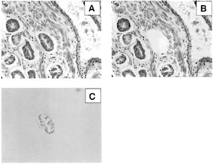 |
| FIGURE 2 Laser capture microdissection of an individual gland in breast ductal carcinoma. (A) H&E stain of heterogeneous human breast tissue, (B) microdissection of the gland of interest, and (C) polymer-cell composite after transfer to film. |
IV. COMMENTS
When using the 30-µm laser spot size, the operator can expect to collect on average five to six cells per laser pulse. Using this information, it is possible to estimate the number of cells captured based on the number of pulses fired during the collection of cells:
| Number of pulses × 5 = total cells captured |
At least three classes of adhesive forces are acting on the selected cells during microdissection: (1) adhesion upward to the locally melted polymer, (2) adhesion laterally to the surrounding tissue elements, and (3) adhesion downward to the glass slide. If adhesive forces #2 and #3 are too great, then microdissection may be incomplete. Lateral adhesive forces are largely a function of the extracellular matrix composition and tissue architecture. The operator does not have much control over lateral adhesive forces. However, slide coatings and treatments can markedly influence adhesion to the glass slide.
- Maintaining upward adhesive forces:
- Tissue sections should be flat and free of folds and wrinkles. Unevenness can prevent proper seating of the polymer cap and limit effective cell capture.
- Incomplete deparaffinization of embedded tissues limits the amount of tissue transferred during microdissection. Deparaffinization times listed are minimal times and, if necessary, may be extended, allowing complete removal of the paraffin from the tissue section.
- Improper focusing of the laser may cause unsuccessful microdissection. The laser should be focused on the 7.5-µm spot size with the 10x objective. The laser should be focused at the beginning of each LCM session and whenever the slide type being used is changed or the cap is repositioned on the slide.
- Limiting lateral adhesive forces: Tissue section thickness should be between 2 and 15µm. Optimal microdissection is achieved with tissue sections cut at 5-8 µm.
- Minimizing downward adhesive forces:
- Use plain, uncharged glass microscope slides for optimal microdissection. While some success has been achieved using poly-L-lysine, silanized, or charged slides with lung tissue, best results for the majority of tissues are obtained with plain glass slides.
- Preparation of frozen sections requires the slides to be frozen at -80°C or to proceed immediately with staining after placing the tissue section onto the slide. Never allow the tissue to dry on the slide. Drying the tissue on the slide makes LCM almost impossible and will denature the analyte molecules.
- Incomplete dehydration of the tissue section prior to LCM limits the operator's success in microdissection. The xylene rinse is essential for complete dehydration of the tissue on the slide. It is imperative that each staining protocol for LCM incorporates a thorough rinse in xylene or xylene substitute. If it is suspected that the slide is not completely dehydrated, allow it to sit in xylene for additional time.
Banks, R. E., Dunn, M. J., et al. (1999). The potential use of laser capture microdissection to selectively obtain distinct populations of cells for proteomic analysis. Electrophoresis 20, 689-700.
Emmert-Buck, M. R., Chuaqui, R., et al. (1996). Laser capture microdissection. Science 274(5289), 998-1001.
Fend, F., Emmert-Buck, M. R., et al. (1999). Immuno-LCM: Laser capture microdissection of immunostained frozen sections for mRNA analysis. Am. J. Pathol. 154, 61-66.
Ornstein, D. K., Englert, C., et al. (2000). Characterization of intracellular prostate-specific antigen from laser capture microdissected benign and malignant prostatic epithelium. Ctin. Cancer Res. 2, 353-356.
Paweletz, C. P., Charboneau, L., et al. (2001). Reverse phase protein microarrays which capture disease progression show activation of pro-survival pathways at the cancer invasion front. Oncogene. 20(16), 1981-1989.
Sgroi, D., Teng, S., et al. (1999). In vivo gene expression profile analysis. Cancer Res. 59, 5656-5661.
Simone, N. L., Bonner, R. F., et al. (1998). Laser capture microdissection: Opening the microscopic frontier to molecular analysis. Trends Genet. 14, 272-276.
Simone, N. L., Paweletz, C. P., et al. (2000). Laser Capture Microdissection: Beyond Functional Genomics to Proteomics. Mole Diag. 5(4), 301-307.
Support our developers


