Negative Staining
Heavy metal negative staining, a now widely used routine technique to prepare biological material for imaging in the transmission electron microscope (TEM), was introduced almost 50 years ago (Brenner and Horne, 1959; for reviews, see Oliver, 1973; Horne, 1991). Suitable specimens may either be in solution or in suspension and thus include the whole spectrum of structural organization of biomolecules, ranging from monomeric and oligomeric proteins [e.g., RNA polymerase (Fig. 1a) or glutamine synthetase (Fig. 1b, bottom)], to protein polymers [e.g., cytoskeletal filaments or the multistranded helical cables of glutamine synthetase (Fig. 1b, top)], and eventually to large multicomponent supramolecular assemblies [e.g., nuclear pore complexes or bacteriophages (Fig. 1c)]. Compared to other electron microscopic techniques, negative staining is remarkably simple and can easily provide reliable structural information as quickly as 2min after preparing the specimen down to resolutions of 2.0nm (reviewed by Bremer et al., 1992) and below (Harris, 1999).
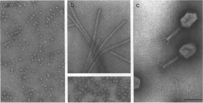 |
| FIGURE 1 From molecules to replicating molecular machines-examples of negatively stained preparations. (a) Monomers of Escherichia coli RNA polymerase holoenzyme. (b) Glutamine synthetase from E. coli. (Top) Helical filaments are formed in the presence of millimolar amounts of Co2+ ions. (Bottom) The intact enzyme molecule is composed of 12 identical 50-kDa subunits that associate with 622 symmetry: i.e., end-on views display a typical blossom-like appearance with six-fold symmetry, whereas side views reveal twofold symmetry. (c) E. coli bacteriophage T4: organization into a distinct prolate icosahedral head and a contractile helical tail to which a base plate with extended fibers is attached at the bottom are evident. RNA polymerase (a) and glutamine synthetase (b) were stained with 0.75% uranyl formate; and bacteriophage T4 (c) was stained with 1% uranyl acetate. Scale bar: 100nm. |
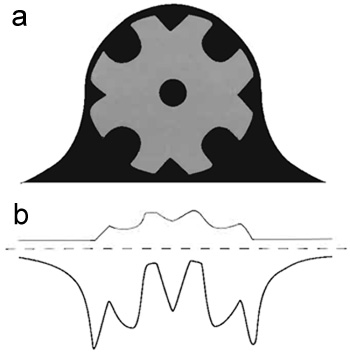 |
| FIGURE 2 Schematic representation of a "negatively stained" model specimen. (a) The schematic view represents a cross section through a model specimen (light grey) that has been embedded in an ideal negative stain (dark grey). (b) The schematic view in a was projected by adding the pixel values along the vertical axis. The projection profile of the "negatively stained" model specimen is represented by a thick black trace, whereas the projection profile of the "unstained" model specimen is depicted by a thinner grey trace. In the case of the "negatively stained" specimen, its projection profile was inverted, i.e., multiplied by-1, to compare it directly with the corresponding profile of the "unstained" specimen. |
As shown schematically in Fig. 2a, a negatively stained specimen is embedded in a microcrystalline heavy atom salt replica that portrays its molecular architecture. Because heavy metal atoms (e.g., U, V, W, Au, Mo, Pt, Pb, Os) scatter electrons much more strongly than elements constituting the biomolecules (i.e., C, H, O, N, P, S), the contrast of negatively stained specimens (Fig. 2b) is much higher than that of unstained specimens and reversed (hence "negative" staining). In addition, the heavy metal salt replica stabilizes the specimen against collapse and distortion and substitutes, at least partially, for the aqueous environment typical for biomolecules. It also serves as a radiation protectant in the sense that it is more radiation resistant than biological matter (cf. Aebi et al., 1984; Bremer and Aebi, 1992).
II. MATERIALS AND INSTRUMENTATION
Negative staining requires only minor investment for instrumentation and supplies. For routine applications, the following items are needed.
- Specimen support grids (Fig. 3a): For example, from Pelco International (www.pelcoint.com). Typically 200-400 mesh/in, copper grids, 3.05 mm in diameter and 0.7 mm thick, coated with a specimen support film (mostly either a carbon/collodion composite film, or a thin carbon film). The specimen grids should be stored dust free, e.g., in a petri dish (Fig. 3b) that is kept at relatively low humidity.
- Precision forceps (Fig. 3c): For example, from Electron Microscopy Sciences (www.emsdiasum.com). It is advisable to bend the jaws of the forceps slightly inwards to prevent surface tension from trapping buffers and solutes between the jaws. A tightly fitting rubber band or piece of plastic tubing allows the jaws to be fixed in the closed state.
- Glow discharge unit (Fig. 3d). It is used to render the support film of the specimen grids hydrophilic and can be built as detailed by Aebi and Pollard (1987). The specimen grid is glow discharged on a small glass block coated with Parafilm (Fig. 3d, arrowhead).
- A metal or plastic tray (Fig. 3e) serves as the "workbench." Drops of water and stain, typically 100 µl each, can be placed on a piece of Parafilm (Fig. 3e, left). Filter or blotting paper (Fig. 3e, right) is required for removing excess liquid from the specimen grid.
- Micropipettes: 5µl and adjustable to 20-200µl or similar.
- A stopwatch is required to control adsorption and staining times.
- A Pasteur pipette drawn out into a capillary and connected to a suction device such as a water jet pump serves to remove excess stain from the specimen grid (Fig. 4f).
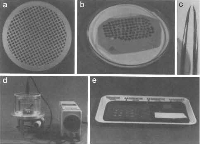 |
| FIGURE 3 Materials and equipment required for negative staining. (a) Specimen support grid (e.g., 200 mesh/in, copper grid, 3.05 mm in diameter and 0.7 mm thick) coated with a collodion-carbon composite film (the support film is particularly evident at the edges). (b) The specimen support grids are stored on filter paper in a covered petri dish (the cover is removed for clarity). (c) Precision forceps with the jaws slightly bent inwards are used for all manipulations. (d) The specimen grids are rendered hydrophilic in a reduced atmosphere of air using a custom-built glow-discharge unit (for the design, see Aebi and Pollard, 1987). The specimen grids are glow discharged on a small glass block that is covered with Parafilm (see arrowhead). (e) A plastic or metal tray serves as the "workbench" for staining. The water and stain drops are placed on a piece of Parafilm on the left, the glass block with a glow discharged grid is seen on right at the back, and a piece of filter paper is depicted in the front. |
Solutions
The following solutions are required for negative staining.
- Specimen solution/suspension
- Deionized or, even better, double-distilled water. Water is required for washing the specimen grid after specimen adsorption.
- Negative stain, i.e., heavy metal solution. For instance, uranyl acetate or sodium phosphotungstate.
A. Preparation of Negative Stain Solution
For the properties of various negative stains, along with references on their preparation, see Bremer et al. (1992). Here, the preparation of uranyl formate, one of the more delicate procedures, is described as an example:
(Mind, uranyl salts are radioactive, cf. p xxx)
Steps
- Weigh out uranyl formate to obtain a final concentration of 0.75% (i.e., 7.5 mg/ml).
- Boil an appropriate amount of water to remove CO2 and to increase the solubility of the uranyl formate in the boiling water.
- Pour the boiling water into a small beaker containing the weighed uranyl formate.
- Stir slowly for 5-10min in the dark (i.e., with the beaker wrapped into aluminum foil).
- Filter the solution through a 0.2-µm membrane filter [e.g., a Supor 0.2-µm Acrodisc 32 from Gelman Sciences (www.pall.com)].
- Adjust the pH to 4.25 by adding 10 N NaOH (about 2µl per 1ml negative stain solution). The uranyl formate solution should turn into a moderately intense yellow (Caution: Increasing the pH toward neutral rapidly leads to precipitation of uranyl salts.)
- Stir for another 5 min in the dark.
- Filter a second time.
- Readjust the volume with double-distilled water to compensate for water loss due to evaporation, filtration, etc.
- Store stain in the dark (e.g., in a tube wrapped into aluminum foil). It will keep stable for 1-2 days.
B. Staining
Our standard staining procedure for soluble proteins and their supramolecular assemblies is illustrated in Fig. 4. As might be appreciated, this procedure is quick, simple, and straightforward.
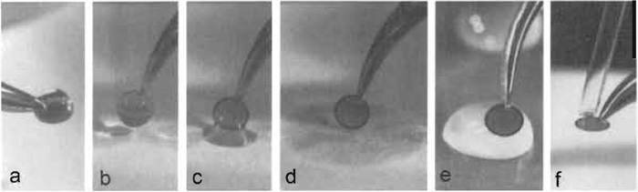 |
| FIGURE 4 Negative staining. (a) A ~5-µl drop of sample solution/suspension is placed onto a glowdischarged specimen support grid that is held horizontally by a pair of forceps and allowed to adsorb for 30-60 s. (b) The specimen grid is then turned vertically and (c) allowed to gently touch the filter paper, which (d) removes excess liquid. (e) The adsorbed specimen is then washed by carefully placing it sideways onto a drop of water for i s, blotted as shown in b-d, and washed a second time. The actual staining is performed similarly by first washing the specimen grid on a drop of negative stain as described in e, blotting and repeating this step once more, this time leaving the specimen grid for 10s on the drop of negative stain solution. (f) After blotting off excess stain, the residual stain is removed by gently moving a capillary (drawn-out and shaped from a Pasteur pipette) around the edge of the grid. The capillary is connected to a low-vacuum suction device (e.g., a water jet pump). |
- Glow discharge specimen grids in a unit such as shown in Fig. 3d, e.g., for 15 s (for details, see Aebi and Pollard, 1987).
- To the freshly glow-discharged specimen grid, apply a 5-µl drop of the sample solution/suspension (Fig. 4a). Let it adsorb for 30-60 s, and then blot off the drop as illustrated in Figs. 4b-4d. For blotting, hold the specimen grid vertical (Fig. 4b) and allow it to touch the filter paper gently (Fig. 4c). The drop will be removed by capillary forces (Fig. 4d).
- Next, wash the specimen grid on a drop of double-distilled water by carefully lowering it sideways onto the surface of the drop (Fig. 4e). After ls, carefully remove the specimen grid from the water drop, blot as shown in Figs. 4b-4d, and repeat this washing regimen once more.
- Finally, stain the specimen for 1s by lowering the specimen grid onto a drop of negative stain solution as described for the washing regimen (Fig. 4e) and then blot the specimen grid as described in Figs. 4b-4d. Repeat this step once; this time, however, leave the specimen grid for 10-15s on the negative stain drop (as illustrated in Fig. 4e) before blotting.
- After blotting off excess stain (Figs. 4b-4d), further reduce the residual stain layer to just a thin (i.e., 50-100nm thick) liquid film prior to air drying. This should be achieved in a controlled fashion; a drawnout and shaped into a slightly bent capillary Pasteur pipette, connected to a suction device such as a water jet pump, is moved gently around the edge of the specimen grid (Fig. 4f). The preparation is now ready for inspection in the EM.
The quality of a negatively stained preparation (i.e., the interpretable structural detail captured on the EM screen, depicted on an electron micrograph, or monitored by a video or slow-scan camera attached to the EM) depends primarily on the penetration properties (e.g., size, charge, and hydrophobicity) of the heavy metal salt used for negative staining and on the physicochemical properties (e.g., solubility, charge, and hydrophobicity) of the specimen. Because some negative stains have a relatively acidic pH, whereas others are neutral or moderately basic and because they may be neutral, anionic, or cationic (for review, see Bremer et al., 1992), negative staining is quite versatile and can be tailored to specific needs.
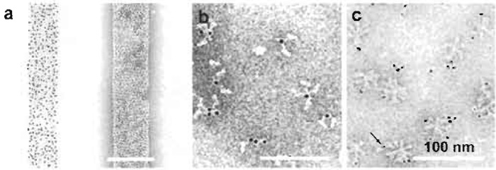 |
| FIGURE 5 Negative staining of Fab-gold and antibody-gold complexes: (a) Bacteriophage T4 polyheads labeled with Fab-Au2.5nm unstained (left) and stained with 1% uranyl acetate. (b) Au3-labled immunoglobulin G bound to bromelain-treated haemagglutinin. (c) Au1-2nm-labeled Fab bound to haemagglutinin rosettes. Arrow: Au1-2nm colloid. (Adapted from Baschong & Wrigley, 1990 |
With tightening safety rules for the use of radioactive substancesmuranyl salts are radioactivem ordering, handling, and disposal of uranyl salts usually have specific guidelines (check with your safety responsible). In turn, the availability of uranyl salts may become more restricted, while novel readymade commercial methylamine-vanadate (Tracz et al., 1997) and methylamine-tungstate-based stains (Shayakhmetov et al., 2000) have been introduced (www.nanoprobes.com, Nanoprobes Inc., Yaphank, NY 11980-9710). As a consequence, nonradioactive metal salts such as tungstates, molybdates and vanadates may be given preference. The performance of such alternatives is best evaluated by trial and error, as illustrated in Figs. 6a-6e by staining bacteriophage T4 polyheads with uranyl formate (a) and prospective alternatives, i.e., with NH4MoO4 (b), NH4VO4 (c), Na2WO4 (d), and RhCl3 (e), and liposomes with methylamine vanadate (f).
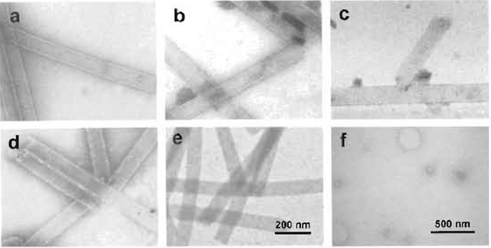 |
| FIGURE 6 Comparative series of prospective negative stains used on bacteriophage T4 polyheads: (a) with 1% uranyl formate, (b) with 2% NH4MoO4, (r with half-saturated NH4VO4, (d) with 1% Na2WO4, and (e) with 2% RhCl3. (f) Liposomes stained with metylamine-vanadate, courtesy of C. Prescianotto-Baschong. |
The negative staining protocol described earlier is suitable for most specimens and stains. With delicate proteins, an additional washing step of the grid with water or sample buffer prior to applying the specimen may be included to wet the specimen support film and to minimize surface tension and/or denaturation of the specimen. The optimal sample concentration, which obviously has to be determined experimentally, should yield well-dispersed and evenly distributed particles adsorbed to the specimen support film. It is determined by the size, shape, and adsorption properties of the biomolecules or supramolecular assemblies under investigation, but also by the washing and staining regimen employed. For oligomers or polymers (e.g., such as filaments), crystalline, or paracrystalline specimens, a higher concentration than for individual biomolecules is required. As a rule of thumb, a few micrograms per milliliter for single particles (see Fig. 1a and bottom of Fig. 1b) and a few hundred micrograms per milliliter for supramolecular assemblies such as filaments (see top of Fig. 1b) or virus particles (see Fig. 1c) usually yield a reasonable particle density on the EM grid. The ionic conditions of the sample buffer and the presence of detergents, while strongly interfering with specimen adsorption, may have little effect on the quality of the negative stain replica surrounding the biomolecules, as long as a sufficient number of washing steps (usually two to six for most compounds) are employed prior to applying the negative stain solution to the specimen.
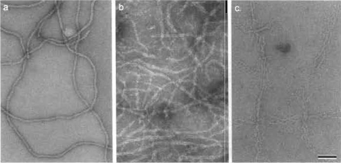 |
| FIGURE 7 Negatively stained human epidermal keratin filaments. (a) Keratin filaments in 10mM Tris, pH 7.5, stained negatively with 0.75% uranyl formate (UF; pH 4.25) appear relatively featureless and compact with a fairly uniform width. (b) In contrast, when the same keratin filaments are stained negatively with 2% sodium phosphotungstate (NaPT; pH 7.0) instead, they locally unravel and exhibit their protofibrillar substructure. (c) Even more dramatic unraveling into their protofibrils occurs when the adsorbed filaments are washed briefly with 10mM phosphate buffer (NaPi; pH 7.0) prior to staining them with 0.75% UF, pH 4.25. Scale bar: 100 nm. |
V. PITFALLS
A. Poor Specimen Adsorption
- Specimen support film is wrongly charged: Highly negatively charged proteins or DNA do adsorb poorly to support films exhibiting a net negative charge as produced by glow discharge in a reduced atmosphere of air. By contrast, glow-discharging specimen grids in a reduced atosphere of pentylamine yield a net positive charge of the support film (cf. Aebi and Pollard, 1987).
- Specimen support film is not properly glow discharged: Try longer glow discharge, and glow discharge only one grid at a time and use it immediately.
- Specimen concentration is too high: A high density of particles adsorbed to the specimen support film renders quantitative and/or controlled removal of excess stain more difficult, thereby resulting in inhomogeneities in the staining even in particle-free areas. Try lower specimen concentration.
- Stain is not sufficiently removed: Try removing stain more quantitatively by suction with a capillary as illustrated in Fig. 4f.
- Suboptimal stain for the specimen: Try a different stain.
- Suboptimal wetting properties of the specimen support film: Try longer glow discharge times or switch to a different sample buffer, assuming that this does not compromise the specimen.
- Incompatibilities between stain and buffers: For instance, uranyl salts precipitate in the presence of inorganic phosphate. Hence avoid using phosphate buffers.
- Buffer contains high molar salt or detergent: Try including more washing steps.
C. "Bubbling" of Stain Upon Irradiation
- Strong recrystallization or water content of stain is too high: Try "prebaking" specimen at a low magnification (e.g., at 1000×) for 3-5s before using higher magnifications.
D. Disintegration of Specimen During Preparation
- Specimen is instable in water (washing steps!): Wash and preequilibrate the specimen with sample buffer instead of water. Replace the conventional buffer with a buffer that will dry off by sublimation when in the electron microscope, such as ammonia acetate. Alternatively, use such a volatile buffer at least for the washing steps. Mild cross-linking with, e.g., 0.05-0.25% glutaraldehyde for 2min on ice (quench with 1% glycine, pH 7.0, or with 1% freshly made NaBH4) may also stabilize the specimen.
- Specimen is in steady-state equilibrium with monomers and/or oligomers: Pellet the specimen (e.g., in a tabletop or air fuge at 100,000g), discard the supernatant, resuspend the pellet in sample buffer, and immediately prepare the grid. Alternatively, fix, e.g., the protein assembly, with 4% formaldehyde while in equilibrum and purify on a sucrose gradient (Baschong et al., 1991).
Acknowledgments
We thank Rosmarie Suetterlin and Daniel Mathys for their help. This work was supported by the Canton Basel-Stadt and the M.E. Müller Foundation of Switzerland)
References
Aebi, U., Fowler, W. E., Buhle, E. L., and Smith, P.R. (1984). Electron microscopy and image processing applied to the study of protein structure and protein-protein interactions. J. Ultrastruct. Res. 88, 143-176.
Aebi, U., Fowler, W. E., Rew, P., and Sun, T.-T. (1983). The fibrillar structure of keratin filaments unraveled. J. Cell Biol. 97, 1131-1143.
Aebi, U., and Pollard, T. D. (1987). A glow discharge unit to render electron microscope grids and other surfaces hydrophilic. J. Electron. Microsc. Tech. 7, 29-33.
Baschong, W., Baschong-Prescianotto, C., Engel, A., Kellenberger, E., Lustig, A., Reichelt R., Zulauf, M., and Aebi U. (1991). Mass analysis of bacteriophage T4 proheads and mature heads by scanning transmission electron microscopy and hydrodynamic measurements. J. Struct. Biol. 106, 93-101.
Baschong, W., Baschong-Prescianotto, C., and Kellenberger, E. (1983). Reversible fixation for the study of morphology and macromolecular composition of fragile biological structures. Eur. J. Cell Biol. 32, 1-6.
Baschong, W., and Wrigley, N. G. (1990). Small colloidal gold conjugated to Fab fragments or to immunoglobulin G as highresolution labels for electron microscopy: A technical overview. J. Electron. Microsc. Tech. 14, 313-323.
Bremer, A., Henn, C., Engel, A., Baumeister, W., and Aebi, U. (1992). Has negative staining still a place in biomacromolecular electron microscopy? Ultramicroscopy 46, 85-111.
Brenner, S., and Home, R. W. (1959). A negative staining method for the high resolution electron microscopy of viruses. Biochim. Biophys. Acta 34, 103-110.
Fassel, T. A., and Graeser, M. L. (1997). Uranyl acetate as a primary fixative for skeletal muscle. Microsc. Res. Tech. 37, 600-601.
Harris, J. R. (1999). Negative staining of thinly spread biological particulates. Methods Mol. Biol. 117, 13-30.
Horne, R. W. (1991). Early developments in the negative staining technique for electron microscopy. Micron Microsc. Acta 22, 321-326.
Oliver, R. M. (1973). Negative stain electron microscopy of protein macromolecules. Methods Enzymol. 27, 616-672.
Shayakhmetov, D. M., Papayannopoulou, T., Stamatoyannopoulos, G., and Lieber, A. (2000). Efficient gene transfer into human CD34+ cells by a retargeted adenovirus vector. J. Virol. 74, 2567-2583.
Tracz, E., Dickson, D. W., Hainfeld, J. F., and Ksiezak-Reding, H. (1997). Paired helical filaments in corticobasal degeneration: The fine fibrillary structure with NanoVan. Brain Res. 773, 33-44.
Support our developers


