×

Read content with fewer ads!

Login- OR -Signup

How Light Behaves


During traveling light waves interact with matter. The consequences of this interaction are that the waves are scattered or absorbed. In the following, we describe the principal behaviors of light.

SCATTERING
Light interaction with matter: the scattering process.
FIGURE 5.2 Light interaction with matter: the scattering process.

Scattering is the process by which small particles suspended in a medium of a different density diffuse a portion of the incident radiation in all directions. In scattering, no energy transformation results, there is only a change in the spatial distribution of the radiation (Figure 5.2).
Light interaction with matter: the scattering process.
FIGURE 5.2 Light interaction with matter: the scattering process.

In the case of solar radiation, scattering is due to its interaction with gas molecules and suspended particles found in the atmosphere. Scattering reduces the amount of incoming radiation reaching the Earth’s surface because significant proportion of solar radiation is redirected back to space.
The amount of scattering that takes place is dependent on two factors: wavelength of the incoming radiation and size of the scattering particle or gas molecule. For small particles compared to the visible radiation, Rayleigh’s scattering theory holds. It states that the intensity of scattered waves roughly in the same direction of the incoming radiation is inversely proportional to the fourth power of the wavelength. In the Earth’s atmosphere, the presence of a large number of small particles compared to the visible radiation (with a size of about 0.5 µm) results such that the shorter wavelengths of the visible range are more intensely diffused. This factor causes our sky to look blue because this color corresponds to those wavelengths. When the scattering particles are very much larger than the wavelength, then the intensity of scattered waves roughly in the same direction of the incoming radiation become independent of wavelength and for this reason, the clouds, made of large raindrops, are white. If scattering does not occur in our atmosphere the daylight sky would be black.

ABSORPTION: LAMBERT–BEER LAW
Some molecules have the ability to absorb incoming light. Absorption is defined as a process in which light is retained by a molecule. In this way, the free energy of the photon absorbed by the molecule can be used to carry out work, emitted as fluorescence or dissipated as heat.
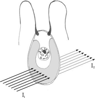


Light absorption by a unicellular alga: II, light incident on the cell and IT, light transmitted by the cell
FIGURE 5.3 Light absorption by a unicellular alga: II, light incident on the cell and IT, light transmitted by the cell
The Lambert–Beer law is the basis for measuring the amount of radiation absorbed by a molecule, a subcellular compartment, such as a chloroplast or a photoreceptive apparatus and a cell, such as a unicellular alga (Figure 5.3). A plot of the amount of radiation absorbed (absorbance, Aλ) as a function of wavelengths is called a spectrum. The Lambert–Beer law states that the variation of the intensity of the incident beam as it passes through a sample is proportional to the concentration of that sample and its thickness (path length). We have adopted this law to measure the absorption spectra in all algal photosynthetic compartments. The Lambert–Beer law states the logarithmic relationship between absorbance and the ratio between the incident (II) and transmitted light (IT). In turn, absorbance is linearly related to the pigment concentration C (mol l-1), the path length l (cm) and the molar extinction coefficient ελ, which is substance-specific and a function of the wavelength.

Light absorption by a unicellular alga: II, light incident on the cell and IT, light transmitted by the cell
FIGURE 5.3 Light absorption by a unicellular alga: II, light incident on the cell and IT, light transmitted by the cell
(5.1)

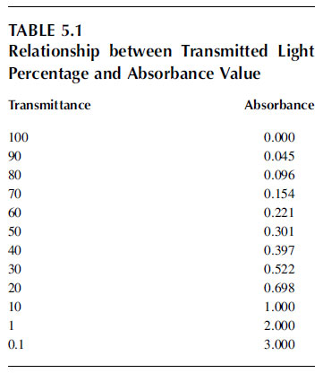
the comparison between transmitted light and absorbance values.
Table 5.1 shows the comparison between transmitted light and absorbance values.

INTERFERENCE
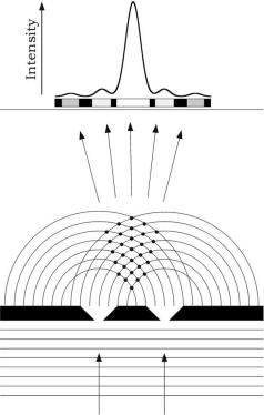
Interference of light passing through two narrow slits, each acting as a source of waves. The superimposition of waves produces a pattern of alternating bright and dark bands. When crest meets crest or
trough meets trough, constructive interference occurs, which makes bright bands; when crest meets trough destructive interference occurs, which makes dark bands. The dots indicate the points of constructive interference. The light intensity distribution shows a maximum that corresponds to the highest number of dots.
FIGURE 5.4 Interference of light passing through two narrow slits, each acting as a source of waves. The superimposition of waves produces a pattern of alternating bright and dark bands. When crest meets crest or trough meets trough, constructive interference occurs, which makes bright bands; when crest meets trough destructive interference occurs, which makes dark bands. The dots indicate the points of constructive interference. The light intensity distribution shows a maximum that corresponds to the highest number of dots.

Electromagnetic waves can superimpose. Scattered waves, which usually have the same frequency, are particularly susceptible to the phenomenon of interference, in which waves can add constructively or destructively. When two waves, vibrating in the same plane, meet and the crests of one wave coincide, with the crests of the other wave, that is, they are in phase, then constructive interference occurs. Therefore, the amplitude of the wave has been increased and this results in the light appearing brighter. If the two waves are out of phase, that is, if the crests of one wave encounter the troughs of the other, then destructive interference occurs. The two waves cancel out each other, resulting in a dark area (Figure 5.4). The interference of scattered waves gives rise to reflection, refraction, diffusion, and diffraction phenomena.
Interference of light passing through two narrow slits, each acting as a source of waves. The superimposition of waves produces a pattern of alternating bright and dark bands. When crest meets crest or
trough meets trough, constructive interference occurs, which makes bright bands; when crest meets trough destructive interference occurs, which makes dark bands. The dots indicate the points of constructive interference. The light intensity distribution shows a maximum that corresponds to the highest number of dots.
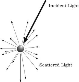
FIGURE 5.4 Interference of light passing through two narrow slits, each acting as a source of waves. The superimposition of waves produces a pattern of alternating bright and dark bands. When crest meets crest or trough meets trough, constructive interference occurs, which makes bright bands; when crest meets trough destructive interference occurs, which makes dark bands. The dots indicate the points of constructive interference. The light intensity distribution shows a maximum that corresponds to the highest number of dots.

Support our developers

Buy Us A Coffee