Drawing chemical structures
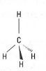 |
| Fig. 42.1 Methane. |
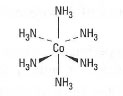 |
| Fig. 42.2 Structure of hexaamminecobaltate.. |
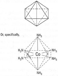 |
| Fig. 42.3 An octahedron. |
- Always draw chemical structures in ink (pencil fades with time).
- Always ensure that the chemical structure is drawn large enough, so that no ambiguity is possible.
- If drawing by hand, ensure that each atom is clearly identified. This may require the use of coloured pens.
- Try and keep the structure as simple as possible, highlighting only the key features.
- Any text should appear in a clear script (by hand or word processed).
- When possible, it is advisable to use computer software packages to generate chemical structures. For example, Figs 42.1-42.4 and 42.6 were generated using ChemWindow®.
- Always indicate the number of chemical bonds.
- Make sure no confusion is possible between different letters of the alphabet representing elements in the Periodic Table.
- If necessary, show the number of electrons (pairs or individual electrons) clearly. Remember, a . (full stop) may be mistaken for a mark in the paper.
- It may be necessary to indicate the structural formula of a molecule, e.g. in isomerism.
Selected examples of drawing chemical structures
Lewis structures
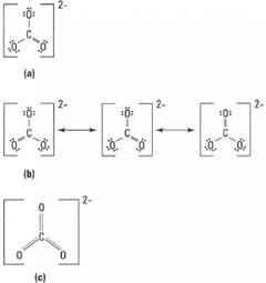 |
| Fig. 42.4 Lewis diagrams for CO32−, |
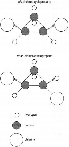 |
| Fig. 42.6 Geometric isomers of dichlorocyclop ropane. |
Ionic structures
In solid-state chemistry it is often necessary to draw a 'unit cell', The most commonly found are the hexagonal close-packed (HCP) crystal structure and cubic close-packed (CCP) crystal structure. In the HCP structure atoms are arranged in an ABABA repeating pattern, while in the CCP structure the arrangement is an ABCABCA pattern. In both cases it is difficult to represent the structures without resorting to the drawing of circles. Fig. 42.S shows the close-packing arrangement for both the HCP and CCP crystal structures. In the HCP structure the first and third layers of atoms are orientated in the same direction (directly above one another) while in the CCP structure, the first and third layers do not coincide, i.e. no atom in the third layer is directly above an atom in the first layer.
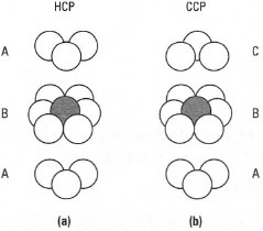 |
| Fig. 42.5 Close-packing arrangement for la) hexagonal close packing (ABABA etc.) and (b) cubic close packing (ABCABCA etc.), |
It is usually not recommended to attempt drawing ionic structures of greater complexity without resorting to a specialized computer-based drawing package.
Isomerism
The importance of drawing chemical structures can be further illustrated by considering isomerism. Isomers are substances that have the same molecular formula but different structural formulae. Different types of isomerism are found in chemistry, e.g. geometric, optical, etc. Fig. 42.6 shows the geometric isomers of dichlorocyclopropane, i.e. cis-dichlorocyclopropane and trans-dichlorocyclopropane.
*Note: It is often important when drawing chemical structures to impart some structural identity.
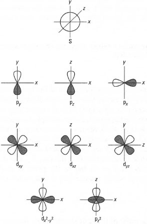 |
| Fig.42.7 Atomic orbitals. |
Atomic orbitals
You may need to draw a visualization of atomic orbitals, usually the s, p and d orbitals. This can be simplified by the use of Cartesian co-ordinates which allow a three-dimensional representation on paper. This is neither easy to replicate or often necessary. A simplified approach is, for example, to replace the spherical s orbital with a circle (Fig. 42.7). Similarly, the three p orbitals can be represented in two dimensions by the use of correct labelling of the axes (Fig. 42.7). Finally, the same approach can be replicated on the five d orbitals (Fig. 42.7). It is worthwhile remembering that the d,y, dxz and dyz orbitals do not reside on the axes (x, y or z), but in the plane of their respective axes. In addition, the dx2 − y2 (it is: x2 − y2)orbital occupies the x- and y-axes and the dz2 (it is: z2) orbital occupies the z-axis.
Electronic configuration
 |
| Fig. 42.8 Electronic configuration. |
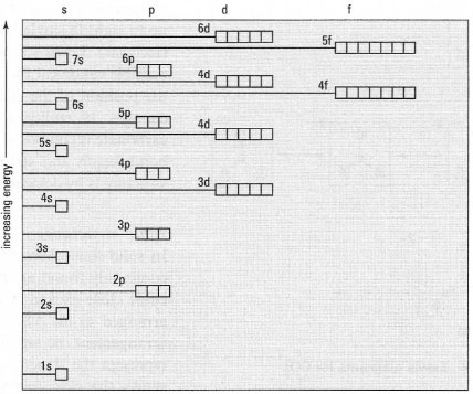
It is often difficult to recollect the order of filling of the electronic structures of atoms of different elements. Fig. 42.8 shows the usual order of filling of the orbitals of an atom according to the Aufbau principle (lowest energy first).
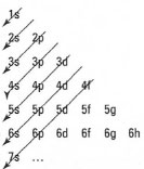 |
| Fig. 42.9 Mnemonic for electronic configuration determination based on the Aufbau principle. |
- s orbitals can have up to 2 e−
- p orbitals can have up to 6 e−
- d orbitals can have up to 10 e−
- f orbitals can have up to 14 e−
|
For example, the atomic number of calcium is 20 (corresponding to 20 electrons). Therefore the electronic configuration is:
| 1s2 2s2 2p6 3s2 3p6 4s2 |
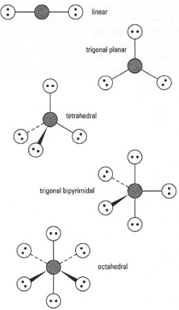 |
| Fig. 42.10 Geometries of molecules. |
This is used to predict the shape of molecules. In order to be able to predict the geometry (or shape) of a molecule several simple steps are required. For example, consider the case of BrF3. In this case we have indicated by underlining that the central atom is bromine. The first step is to determine the number of valence electrons for bromine; this is done by establishing the electron configuration for bromine, i.e. 1s2 2s2 2p6 3s2 3p6 4s2 3d10 4p5. We can determine that the number of outer electrons is seven (from 4s2 and 4p5). We then determine how many atoms are attached to the central bromine atom - the answer is three. By simple addition we have 7 + 3 = 10 electrons. We know that two electrons are required per bond; therefore we have enough electrons for five bonds. Then, it is simply the case to determine a geometry that allows for five bonds to be at the maximum distance from each other. Commonly, five different arrangements of atoms are found: linear, trigonal planar, tetrahedral, trigonal bipyramidal and octahedral. These arrangements are shown in Fig. 42.10. We can therefore see that the geometry of BrF3 is trigonal bipyramidal. VSEPR also works for anions and cations using the same procedure. For a cation, a positively charged species, simply deduct one electron from the total; similarly for an anion, a negatively charged species, add one electron to the total. In all cases the total number of electrons obtained will be an even number.
Molecular orbital diagrams
Molecular orbital diagrams (see Fig. 42.11) are required in the study of chemical bonding. For a diatomic molecule these consist of two atomic orbitals (AOs) and two molecular orbitals (MOs). In the case of the two MOs, one is the bonding MO and the other the anti-bonding MO. An asterisk (*) is used to represent an anti-bonding MO. Bonding MOs (of lower energy) are always occupied first.
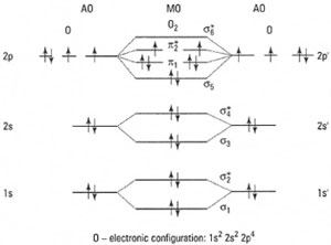 |
| Fig. 42.11 Molecular orbital diagram for oxygen. |
Support our developers


