Vacuum or reduced-pressure distillation
Distillation at reduced pressure is used to distil liquids with few impurities or
to fractionate the components of liquid mixtures with high boiling points,
which would decompose if distilled at atmospheric pressure. The
modifications to the distillation apparatus (Fig. 15.1) required for reducedpressure
distillation are:
- A vacuum source: this can be a water pump with an 'anti-suckback'
trap producing a vacuum of 15-25 mm Hg, at best; or a rotary vacuum
pump (consult your instructor about its use since it is an expensive piece of
equipment and easily contaminated or damaged), which will evacuate down
to 0.1mm Hg. Two-stage dry vacuum pumps produce a vacuum of 1-5mm
Hg, are resistant to organic and acid vapours and are easy to use.
- A manometer to measure the pressure (vacuum) in the apparatus, since the
boiling point of a liquid varies with pressure. Two types are in common use
(Fig. 15.3): the Anschutz manometer, which gives a constant reading of the
vacuum throughout the distillation, and the Vacustat®, which is used to
take a 'sample' of the vacuum at a given instant. Vacustats® are very
accurate and are more often used in combination with a rotary oil pump.
- A take-off adapter, which permits the collection of several fractions
without stopping the distillation to change the receiving flasks. A
receiving adapter, termed a 'pig' (Fig. 15.4), can be rotated on the end of
the condenser to collect three fractions.
- Appropriate 'anti-bumping' measures: reduced-pressure distillations are
notoriously prone to 'bumping' and anti-bumping granules are
ineffective. You can use a magnetic 'flea' in conjunction with a hot platestirrer
and oil bath; an air bleed, made by pulling out a Pasteur pipette
into a fine capillary using a microburner (consult your instructor),
inserting it into a screwcap adapter and placing it in the second
neck of the distilling flask. The vacuum pulls a fine stream of air into the flask and forms small bubbles which agitate the liquid during distillation;
or a wooden boiling stick for small-scale distillations of short duration,
since the vacuum will pull air from the stick and agitate the liquid.
- A three-way tap inserted between the vacuum source and the manometer,
so that you can control the vacuum applied to the distillation system.
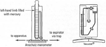 |
| Fig. 15.3 Manometers for vacuum distillation. |
|
|
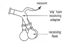 |
| Fig. 15.4 'Pig'-type receiving flask adapter. |
|
A typical system for reduced-pressure distillation is shown in Fig. 15.5 and
the procedure, using a water pump, is described in Box 15.4.
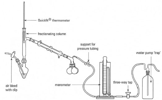 |
| Fig. 15.5 Apparatus for vacuum distillation. |
Kugelrohr distillation
This is also known as short-path distillation or bulb-to-bulb distillation. It is a
procedure for reduced-pressure distillation, which almost eliminates losses
owing to the size of the apparatus, and is particularly useful for small volumes of
liquids. The liquid sample is placed in a small round-bottom flask, connected to
a series of bulbs (Fig. 15.6) and then heated and rotated (to prevent bumping) under vacuum in an electric oven. The liquid distils from the flask inside the
oven to a cold bulb outside the oven. Since the distillation path is very short the
length of a ground-glass joint losses are minimized. The use of several bulbs as
receiver flasks allows a small volume of mixture to be fractionated by varying
the temperature in the oven. The distillates can be removed from the bulbs by
either washing into another flask with a low-boiling-point solvent or using a
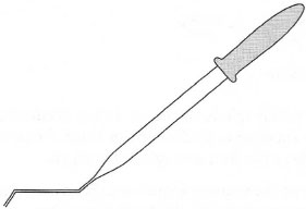
'bent' Pasteur pipette (Fig. 15.7) since the bulbs can only be held horizontally.
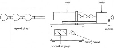 |
| Fig. 15.6 Kugelrohr distillation apparatus. |
|
|
|
| Fig. 15.7 A 'bent' Pasteur pipette. |
|
Steam distillation
This process can be used to separate water-insoluble covalent compounds
from crude reaction mixtures or to isolate volatile natural products, e.g.
terpenes from plant tissue. The crude mixture is heated with water and steam
and the steam-volatile material eo-distils with the steam and is then
condensed with the water and collected. You will then need to carry out an
extraction to separate the water and the insoluble component.
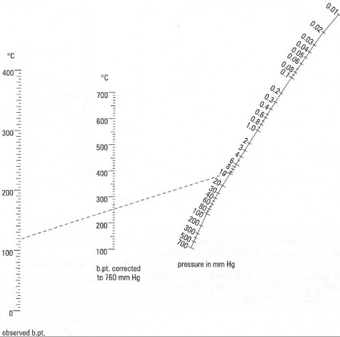 |
| Fig. 15.8 Nomograph for estimating boiling point at reduced pressure. To use it, draw a line between the recorded pressure and the boiling point at 760 mm Hg, and then extend the line to the observed boiling point scale. This point is the boiling point at the reduced pressure. In this example, a liquid b.pt. of 250QCat 760 mm Hg will boil at 118°C at 10 mm Hg. |
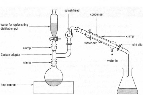 |
| Fig. 15.9 Apparatus for steam distillation. |
The steam required for a steam distillation can be provided by an external
source, such as piped steam in the laboratory or steam generated by heating
water in a flask, which is then piped into the distilling flask. Steam is very
dangerous and the safest way to generate steam is to heat the compound with
a vast excess of water in the distilling flask: steam is generated in situ. The
equipment for steam distillation is illustrated in Fig. 15.9 and the procedure
is described in Box 15.5.
*Note: You must never attempt a distillation in a completely
closed system. Always check that the expanding vapours can escape.


