Atomic Absorption Spectroscopy
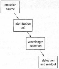
The components of an atomic absorption spectrometer are a radiation source, an atomization cell, a sample introduction system, a method of wavelength selection and a detector (Fig. 27.2).Radiation source
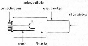
The main radiation source for AAS is the hollow-cathode lamp (HCL). The HCL (Fig. 27.3) emits radiation characteristic of a particular element. The choice of HCL for AAS is simple. For example, if you are analysing for lead, you will need a lead-coated HCL. It is normal to pre-warm the HCL for about 10min prior to use. This can be done either by using a separate pre-heater unit, capable of warming up several HCLs simultaneously, or by inserting the HCL in the AAS instrument and switching on the current. The lamp is typically operated at an electric current between 2 and 30 mA.
|
|
Atomization cell
Several types of atomization cell are available: flame, graphite furnace, hydride generation and cold vapour. Flame is the most common. In the premixed laminar flame, the fuel and oxidant gases are mixed before they enter the burner (the ignition site) in an expansion chamber. The more commonly used flame in FAAS is the air-acetylene flame (temperature, 2500 K), while the nitrous oxide-acetylene flame (temperature, 3150 K) is used for refractory elements, e.g. AI. Both are formed in a slot burner positioned in the light path of the HCL (Fig. 27.4).
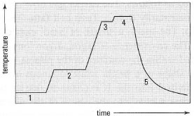
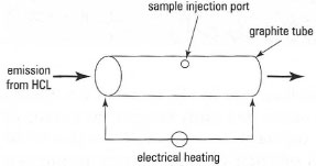
In the graphite furnace atomizer, a small volume of sample (5-100,&micrp;L) is introduced onto the inner surface of a graphite tube (or onto a platform placed within the tube) through a small opening (Fig. 27.5). The graphite tube is arranged so that light from the HCL passes directly through the centre. Passing an electric current through the tube allows the operator to program a heating cycle, with several stages (Fig. 27.6) including the elimination of water from the sample (drying), removal of the sample matrix (ashing), atomization of the analyte (analysis), and removal of extraneous material (cleaning). An internal gas flow of inert gas (N2 or Ar) during the drying and ashing stages removes any extraneous material.
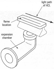 |
| Fig.27.4 Components of a slot burner for FAAP. |
| ⇒ Equation [27.1] | 3BH4− + 3H+ + 4H3AsO3 → 3H3BO3 + 4AsH3 + 3H2O |
Cold vapour generation is the term exclusively reserved for mercury. Mercury in a sample is reduced to elemental mercury by tin (II) chloride (eqn 27.2):
| ⇒ Equation [27.2] | SN2+ + Hg2+ → SN4+ + Hg0 |
and the mercury vapour produced is transported to an atomization cell by a carrier gas. The atomization cell consists of a long-path glass absorption cell located in the path of the HCL. Mercury is monitored at a wavelength of 253.7 nm.
|
|
Sample introduction into the flame
Samples are almost exclusively introduced into flames as liquids. Solid samples need to be converted to aqueous solutions using methods such as decomposition. Once in the aqueous form the sample is introduced into the flame using a nebulizer/expansion chamber.
The pneumatic concentric nebulizer consists of a stainless steel tube through which a Pt/Ir capillary tube is located. The aqueous sample is drawn up through the capillary tube by the action of the oxidant gas (air) escaping through the exit orifice that exists between the outside of the capillary tube and the inside of the stainless steel tube. The action of the escaping air and aqueous sample is sufficient to form a coarse aerosol in a process termed the Venturi effect. The typical uptake rate of the nebulizer is between 3 and 6 mL min−1.
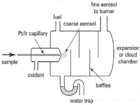 |
| Fig.27.7 Schematic diagram of a nebulizerexpansion chamber for FAAS. |
- to convert the aqueous sample solution into a coarse aerosol using the oxidant gas;
- to disperse the coarse aerosol further into a fine aerosol, by interaction with baffles located within the chamber;
- to condense any residual aerosol particles, which then go to waste.
Wavelength selection and detection
As AAS is used to monitor one metal at a time, the spectrometer used is termed a monochromator. Two optical arrangements are possible; single and double beam. The latter is preferred as it corrects for fluctuations in the HCL caused by warm-up, drift and source noise, thus leading to improved precision in the absorbance measurement. A schematic diagram of the optical arrangement is shown in Fig. 27.8. The attenuation of the HCL radiation by the atomic vapour is detected by a photomultiplier tube (PMT), a device for proportionally converting photons of light to electric current.
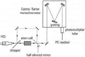 |
| Fig. 27.8 Schematic diagram of the optical arrangement for AAS. |
Background correction methods
One of the main practical problems with the use of AAS is the occurrence of molecular species that coincide with the atomic signal. One approach to remove this molecular absorbance is by the use of background correction methods. Several approaches are possible, but the most common is based on the use of a continuum source, D2. In the atomization cell (e.g. flame) absorption is possible from both atomic species and from molecular species (unwanted interference). By measuring the absorption that occurs from the radiation source (HCL) and comparing it with the absorbance that occurs from the continuum source (D2) a corrected absorption signal can be obtained. This is because the atomic species of interest absorb the specific radiation associated with the HCL source, whereas the absorption of radiation by the continuum source for the same atomic species will be negligible.
Interferences in the flame
Interferences in the flame can be classified into four categories: chemical, ionization, physical and spectral.
Chemical interferences occur when the analyte forms a thermally stable compound with a molecular or ionic species present in the sample solution. Examples include the suppression of alkaline earth metals due to the presence of phosphate, silicate or aluminate in the sample solution in the air-acetylene flame. The most well-known example of this is the absorption signal suppression that occurs for Ca at 422.7nm owing to increasing amounts of phosphate. This signal suppression is due to the formation of calcium pyrophosphate, a thermally stable compound in the flame.
Ionization interferences occur most commonly for alkali and alkaline earth metals. The low ionization potential of these metals can lead to their ionization in the relatively hot environment of the flame. If this occurs, no absorption signal is detected, since FAAS is a technique for measuring atoms not ions. This process can be prevented by the addition of an ionization suppressor or 'buffer', e.g. an alkali metal such as Cs. Addition of excess Cs leads to its ionization in the flame in preference to the metal of interest, e.g. Na. This process is termed the 'mass action' effect.
Physical interferences are due to the effects of the sample solution on aerosol formation within the spray chamber. The formation of an aerosol is dependent upon the surface tension, density and viscosity of the sample solution. This type of interference can be controlled by the matrix matching of sample and standard solutions, i.e. add the same sample components to the standard solution, but without the metal of interest. If this is not possible, it is then necessary to use the method of standard additions (Box 27.3).
Spectral interferences are uncommon in AAS owing to the selectivity of the technique. However, some interferences may occur, e.g. the resonance line of Cu occurs at 324.754 nm and has a line coincidence from Eu at 324.753 nm. Unless the Eu is 1000 times in excess, however, it is unlikely to cause any problems for Cu determination. In addition to atomic spectral overlap, molecular band absorption can cause problems, e.g. calcium hydroxide has an absorption band on the Ba wavelength of 553.55 nm while Pb at 217.0 nm has molecular absorption from NaCl. Molecular band absorption can be corrected for using background correction techniques. The operation of a flame atomic absorption spectrometer is described in Box 27.6.
Support our developers


