Inductively coupled plasma
A radio frequency inductively coupled plasma (ICP) is formed within the confines of three concentric glass tubes or plasma torch (Fig. 27.9). Each concentric glass tube has a tangentially arranged entry point through which argon gas enters the intermediate (plasma) and external (coolant) tubes. The inner tube consists of a capillary tube through which the aerosol is introduced from the sample introduction system. Located around the plasma torch is a coil of water-cooled copper tubing. Power input to the ICl? is achieved through this copper, load or induction coil, typically in the range 0.5-1.5 kW at a frequency of 27 or 40MHz.Initiation of the plasma is achieved as follows. The carrier gas flow is first switched off and a spark added momentarily from a Tesla coil (attached to the outer edge of the plasma torch). The spark, a source of 'seed' electrons, causes ionization of the argon gas. The co-existence of argon, argon ions and electrons constitutes a plasma located within the confines of the plasma torch but protruding from the top in the shape of a bright white luminous bullet. In order to introduce the sample aerosol into the ICP (7000-10 000 K) the carrier gas is switched on and punches a hole into the centre of the plasma creating the characteristic doughnut or toroidal shape. The emitted radiation is viewed laterally (side-on) through the luminous plasma.
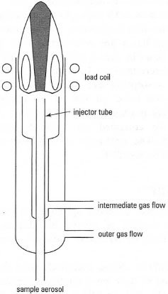 |
| Fig. 27.9 Schematic diagram of an inductively coupled plasma. |
Sample introduction
The most common method of liquid sample introduction in ICP-AES is the nebulizer. The nebulizer operates in the same manner as that used for FAAS but there are differences in its construction material and manufactured tolerance (the nebulizer for ICP-AES generates a finer aerosol, but is more inefficient). The pneumatic nebulizer consists of a concentric glass tube through which a capillary tube passes (Fig. 27.10). The sample is drawn up through the capillary by the action of the argon carrier gas escaping through the exit orifice that exists between the outside of the capillary tube and the inside of the glass concentric tube. The typical uptake rate of the nebulizer is between 0.5 and 4 mL min−. In common with FAAS, a means to reduce the coarse aerosol generated to a fine aerosol is required. In ICP-AES terminology this device is called a spray chamber (Fig. 27.11).
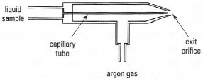 |
| Fig. 27.10 Schematic diagram of a pneumatic nebulizer. |
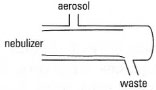 |
| Fig. 27.11 Schematic diagram of a spray chamber. |
The nature of the ICP is such that all elemental information from the sample is contained within it. The only limitation is whether it is possible to observe all the elemental information at the same time or one element at once. This limitation is associated not with the ICP but with the type of spectrometer used to view the emitted radiation. A monochromator allows measurement of one wavelength, corresponding to one element at a time, while a polychromator allows multiwavelength or multielement detection. The former can perform sequential multielement analysis, while the latter carries out simultaneous multielement analysis. The typical wavelength coverage required for a spectrometer is between 167nm (AI) and 852nm (Cs).
Detectors
The most common detector for AES is the photomultiplier tube. An alternative approach for the detection of multielement (multiwavelength) information is the charged-coupled device (CCD). A CCD is essentially an array of closely spaced metal-insulator-semiconductor diodes formed on a wafer of semiconductor material. Incident light striking the CCD is converted into an electrical signal.
Interferences in ICP-AES
Interferences for AES can be classified into two main categories, spectral and matrix interferences. Spectral interference can occur as a result of an interfering emission line from either another element or the argon source gas, impurities within or entrained into the source, e.g. molecular species such as N2. Such interferences can be eliminated or reduced either by increasing the resolution of the spectrometer or by selecting an alternative spectral emission line.
Matrix interferences are often associated with the sample introduction process. For example, pneumatic nebulization can be affected by the dissolved-solids content of the aqueous sample, which affects the uptake rate of the nebulizer and hence the sensitivity of the assay. Matrix effects in the plasma source typically involve the presence of easily ionizable elements (EIEs), e.g. alkali metals, within the plasma source.
Support our developers


